 plumi
Alternating currents: Eduqas A‑Level Physics questions
Every Eduqas A-Level Physics exam question on 3.A Alternating currents, 2016–2025, with its mark scheme and examiner’s report.
Find questions1,592
Calculations
Q9(a)(i)
The whole paper ↗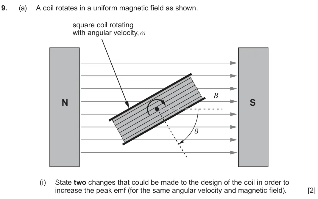
Q9(a)(ii)
The whole paper ↗
Q9(a)(iii)
The whole paper ↗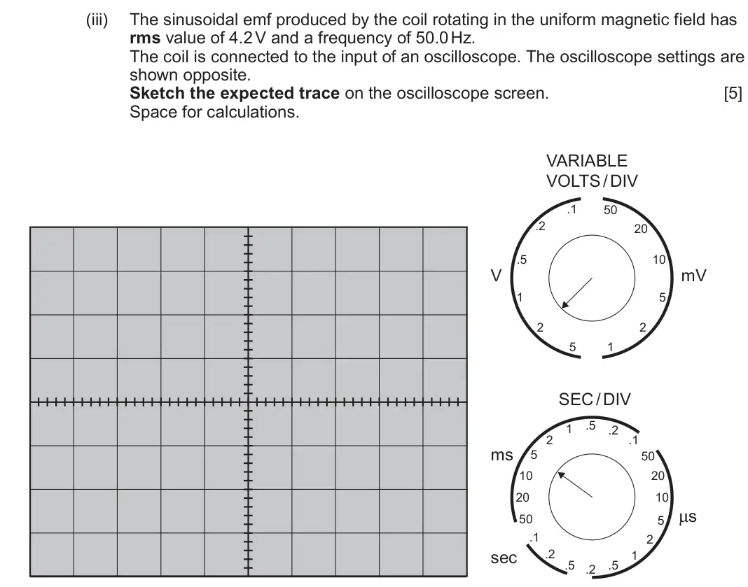
Q9(b)
The whole paper ↗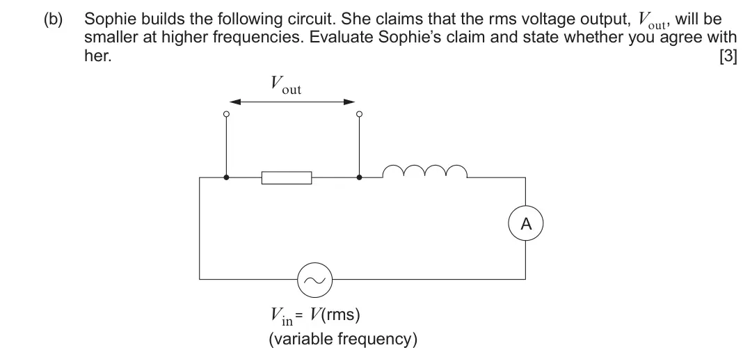
Q9(c)(i)
The whole paper ↗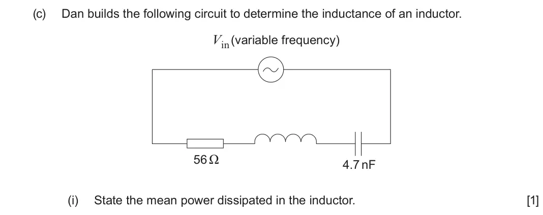
Q9(c)(ii)
The whole paper ↗
Q9(c)(iii)
The whole paper ↗
Q9(c)(iv)
The whole paper ↗
Q9(a)(i)
The whole paper ↗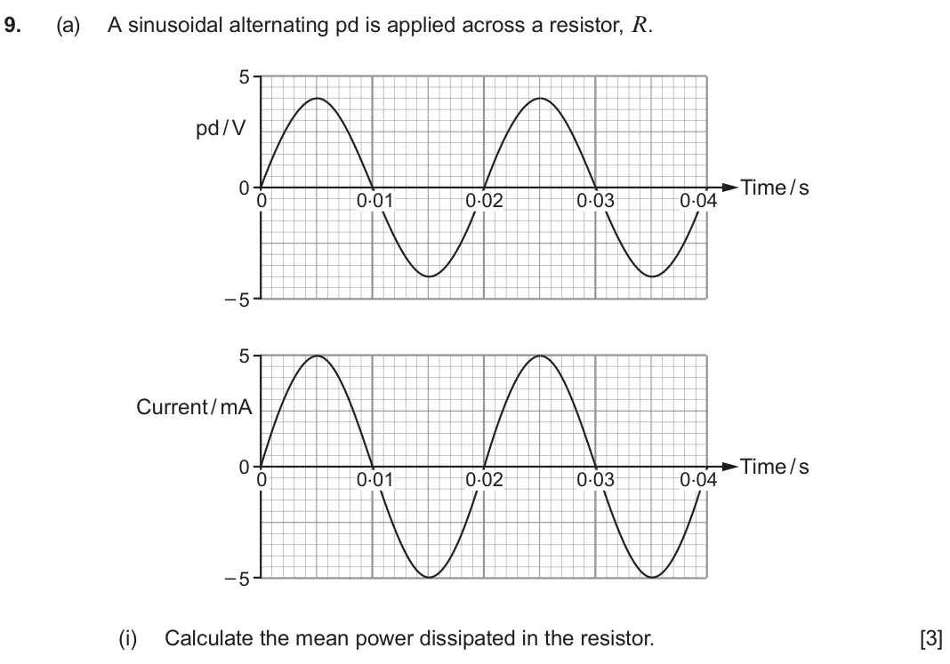
Q9(a)(ii)
The whole paper ↗
Q9(a)(iii)
The whole paper ↗
Q9(b)
The whole paper ↗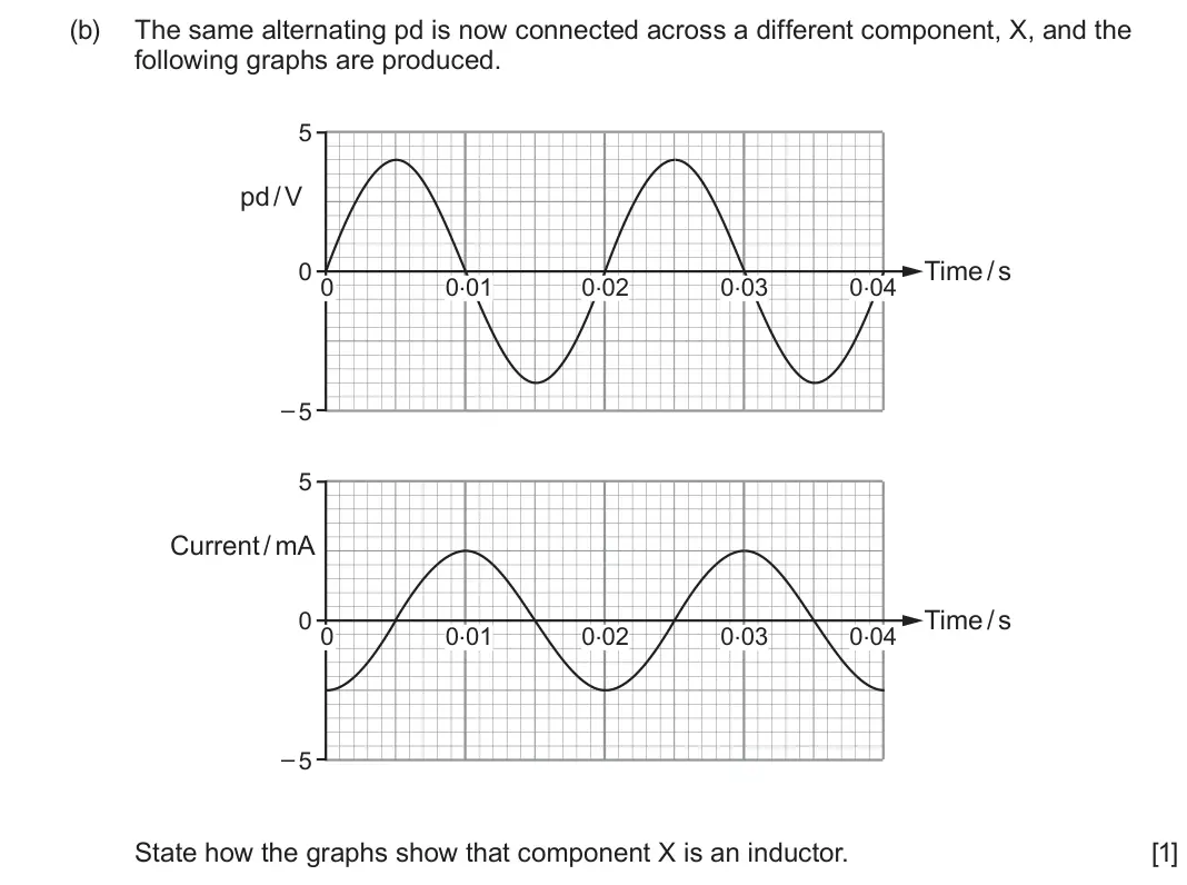
Q9(c)(i)
The whole paper ↗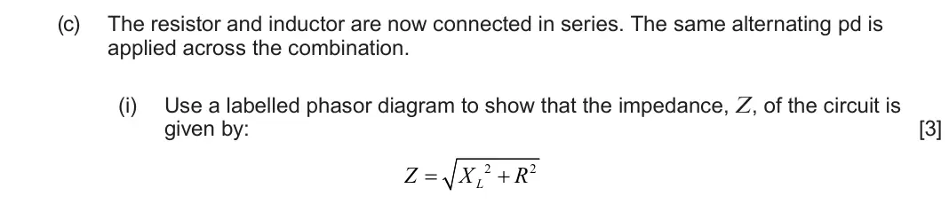
Q9(c)(ii)
The whole paper ↗
Q9(d)(i)
The whole paper ↗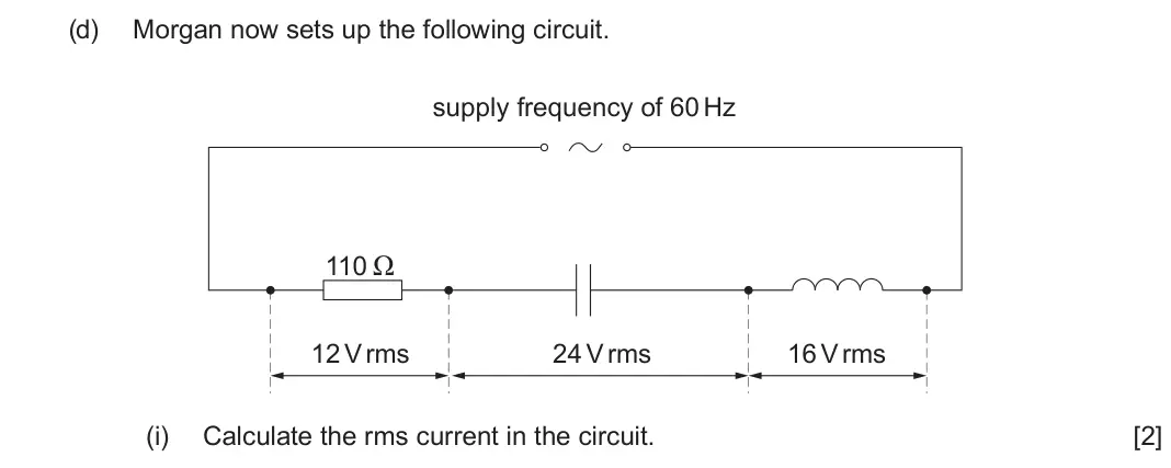
Q9(d)(ii)
The whole paper ↗
Q11(a)(i)
The whole paper ↗
Q11(a)(ii)
The whole paper ↗
Q11(a)(iii)
The whole paper ↗
Q11(b)(i)
The whole paper ↗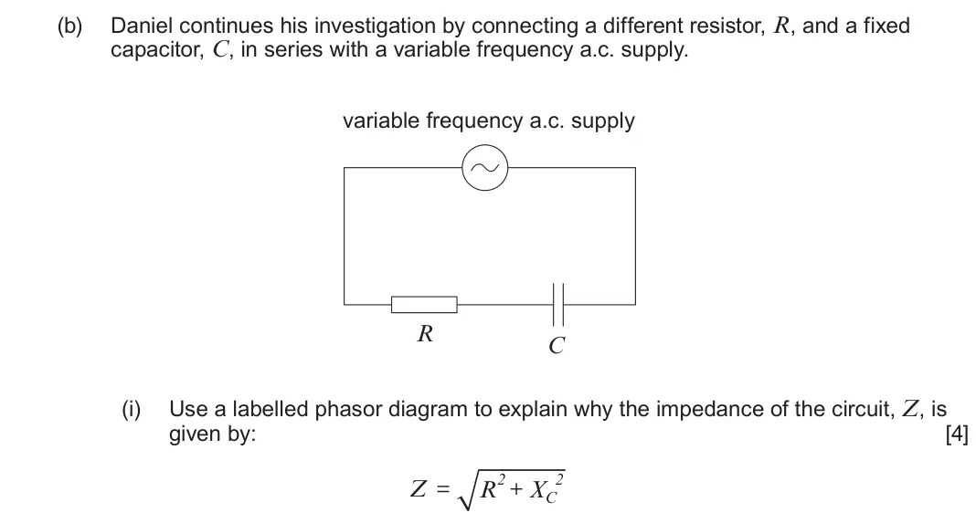
All 57 questions on Alternating currents, as a list
- June 2025, Component 3, Q9(a)(i) (2 marks): State two changes that could be made to the design of the coil in order to increase the peak emf (for the same angular velocity and magnetic field). [2]
- June 2025, Component 3, Q9(a)(ii) (1 mark): Write an equation for the peak emf induced in a rotating coil. [1]
- June 2025, Component 3, Q9(a)(iii) (5 marks): The sinusoidal emf produced by the coil rotating in the uniform magnetic field has rms value of 4.2 V and a frequency of 50.0 Hz. The coil is connected to the i
- June 2025, Component 3, Q9(b) (3 marks): Sophie builds the following circuit. She claims that the rms voltage output, Vout, will be smaller at higher frequencies. Evaluate Sophie’s claim and state whet
- June 2025, Component 3, Q9(c)(i) (1 mark): State the mean power dissipated in the inductor. [1]
- June 2025, Component 3, Q9(c)(ii) (4 marks): When the frequency of Vin is equal to 15 kHz, the rms current is at its maximum. Determine the value of the inductance of the inductor. [4]
- June 2025, Component 3, Q9(c)(iii) (3 marks): Calculate the Q factor of the circuit. [3]
- June 2025, Component 3, Q9(c)(iv) (1 mark): State the effect of increasing the Q factor on the resonance curve. [1]
- June 2024, Component 3, Q9(a)(i) (3 marks): Calculate the mean power dissipated in the resistor. [3]
- June 2024, Component 3, Q9(a)(ii) (2 marks): Calculate the energy dissipated per cycle in the resistor. [2]
- June 2024, Component 3, Q9(a)(iii) (2 marks): Determine the number of times per second the instantaneous power dissipation in the resistor reaches a maximum. [2]
- June 2024, Component 3, Q9(b) (1 mark): The same alternating pd is now connected across a different component, X, and the following graphs are produced. 5 pd / V 0 0 Time / s 0.01 0.02 0.03 0.04 – 5 5
- June 2024, Component 3, Q9(c)(i) (3 marks): Use a labelled phasor diagram to show that the impedance, Z, of the circuit is given by: [3] Z X 2 R 2 L
- June 2024, Component 3, Q9(c)(ii) (4 marks): Morgan knows that no power is dissipated in an inductor with zero resistance. He therefore claims that adding the inductor will not affect the mean power dissip
- June 2024, Component 3, Q9(d)(i) (2 marks): Calculate the rms current in the circuit. [2]
- June 2024, Component 3, Q9(d)(ii) (3 marks): Hence, calculate the value of the capacitor. [3]
- June 2023, Component 3, Q11(a)(i) (2 marks): Show, in clear steps, that the resonance frequency, f0, of the circuit is given by: [2] 1 f0 = π 2 LC
- June 2023, Component 3, Q11(a)(ii) (2 marks): Calculate the maximum possible resonance frequency for the circuit. [2]
- June 2023, Component 3, Q11(a)(iii) (2 marks): Explain why the maximum rms current in this circuit is approximately 5 A. [2]
- June 2023, Component 3, Q11(b)(i) (4 marks): Use a labelled phasor diagram to explain why the impedance of the circuit, Z, is given by: [4] R2 2 Z = + XC
- June 2023, Component 3, Q11(b)(ii) (2 marks): Hence show that: [2] 1 Z2 = + R2 ω2 C2
- June 2023, Component 3, Q11(b)(iii) (5 marks): Using the circuit, Daniel determines Z for a number of different values of ω and plots a graph of Z2 against 1 ω2 . 14.0 Z2 / Ω2 12.0 10.0 8.0 6.0 4.0 2.0 0 0 5
- June 2023, Component 3, Q11(b)(iv) (3 marks): While carrying out the investigation, Daniel notices that the pd across the resistor, VR, is small at low frequencies and approaches the supply pd at high frequ
- Autumn 2021, Component 3, Q9(b)(i) (1 mark): Show that the resonance frequency of the circuit above is approximately 10 000 Hz. [1]
- Autumn 2021, Component 3, Q9(b)(ii) (1 mark): Explain why the maximum rms current is approximately 50 mA. [1]
- Autumn 2021, Component 3, Q9(b)(iii) (3 marks): Show that the rms current in the circuit is approximately 17 mA when the frequency is 16 kHz. [3]
- Autumn 2021, Component 3, Q9(b)(iv) (3 marks): Use the results of parts (i), (ii) and (iii) to sketch a graph of rms current against frequency for the circuit on the axes provided. [3] 120 rms current / mA 1
- Autumn 2021, Component 3, Q9(c) (5 marks): Caitlin claims that the graph below shows the variation of rms current with frequency for the RCL circuit shown (the same circuit as in part (b) but with the re
- Autumn 2020, Component 3, Q11(a) (3 marks): With the aid of a phasor diagram, explain why the impedance of an RCL circuit is given by: [3] 2 + R2 ( ) Z = XL − XC
- Autumn 2020, Component 3, Q11(b)(i) (3 marks): Show that the combined magnitude of the reactance of the inductor and capacitor is the same (to 3 s.f.) as the resistance of the resistor when the frequency is
- Autumn 2020, Component 3, Q11(b)(ii) (3 marks): Hence, calculate the rms current in the circuit when the frequency is 4 150 Hz. [3]
- Autumn 2020, Component 3, Q11(b)(iii) (1 mark): Calculate (or state) the phase angle between the applied pd and the current when the frequency is 4 150 Hz. [1]
- Autumn 2020, Component 3, Q11(b)(iv) (3 marks): The resonance frequency of the RCL circuit is approximately 9 800 Hz. By sketching a graph of rms current against frequency, explain why there is a second highe
- Autumn 2020, Component 3, Q11(b)(v) (2 marks): This second frequency occurs when the magnitude of the reactances of the inductor and capacitor are reversed from those in part (b)(i). Use this information to
- Autumn 2020, Component 3, Q11(c) (5 marks): Robyn is required to produce a wave trace on an oscilloscope for an a.c. power supply of frequency 3.0 kHz and rms pd 0.60 V. Deduce whether or not the settings
- June 2019, Component 3, Q11(a) (3 marks): Derive the expression for the resonance frequency, f0, of a series RCL circuit. [3] 1 f0 = 2π LC
- June 2019, Component 3, Q11(b)(i) (1 mark): Calculate the rms current at the resonance frequency (f0). [1]
- June 2019, Component 3, Q11(b)(ii) (4 marks): Calculate the rms current at twice the resonance frequency (2f0). [4]
- June 2019, Component 3, Q11(b)(iii) (2 marks): Calculate the Q factor of the RCL circuit. [2]
- June 2019, Component 3, Q11(b)(iv) (3 marks): Sketch a graph of the rms current in the RCL circuit versus applied frequency of the a.c. supply on the axes provided. Label this graph 28 Ω. [3] rms current /
- June 2019, Component 3, Q11(b)(v) (2 marks): The 28 Ω resistor is replaced by a 56 Ω resistor. On the same axes, sketch and label a second graph showing the rms current versus frequency for the new circuit
- June 2019, Component 3, Q11(c) (5 marks): Morgan claims that the rms output pd (Vout) in the following circuit is greater than 4.25 V when the frequency is greater than 82.5 Hz but less than 4.25 V belo
- June 2018, Component 3, Q11(a)(i) (2 marks): Calculate the rms pd of the oscilloscope trace shown. [2]
- June 2018, Component 3, Q11(a)(ii) (2 marks): Calculate the frequency of the oscilloscope trace shown. [2]
- June 2018, Component 3, Q11(b)(i) (2 marks): Use Faraday’s Law to explain why the peak emf induced in the coil is proportional to the angular velocity of rotation of the coil. [2]
- June 2018, Component 3, Q11(b)(ii) (2 marks): Use Faraday’s Law to explain why the emf induced in the coil depends on the angle, θ. [2]
- June 2018, Component 3, Q11(c)(i) (2 marks): In the following LCR circuit, explain why the rms resonance current is 125 mA. [2] variable frequency a.c. supply Vrms = 15 V 120 Ω 24 mH 4.2 nF
- June 2018, Component 3, Q11(c)(ii) (2 marks): Calculate the resonance frequency of the circuit. [2]
- June 2018, Component 3, Q11(c)(iii) (3 marks): Show that the rms current is 42 mA when the frequency of the supply is 17 kHz. [3]
- June 2018, Component 3, Q11(c)(iv) (5 marks): Alistair claims that the mean power dissipation in the circuit at 17 kHz is: P = IrmsVrms = 0.042 × 15 = 0.63 W Another student Michonne states that the correct
- June 2017, Component 3, Q10(a)(i) (2 marks): the rms current; [2]
- June 2017, Component 3, Q10(a)(ii) (2 marks): the resistance of the toaster. [2]
- June 2017, Component 3, Q10(b) (5 marks): Helen claims that the following circuit will have a minimum impedance of 68 Ω when the frequency is very low but that the impedance will be extremely large at h
- June 2017, Component 3, Q10(c)(i) (2 marks): Explain why the rms current at resonance of the following circuit is approximately 700 mA. [2] variable frequency a.c. supply Vrms = 12 V 18 Ω 5.2 mH 13.5 μF
- June 2017, Component 3, Q10(c)(ii) (2 marks): Show that the resonance frequency (f0) is approximately 600 Hz. [2]
- June 2017, Component 3, Q10(c)(iii) (4 marks): Calculate the rms current when the frequency of the supply is increased to 1.5 f0 [4]
- June 2017, Component 3, Q10(c)(iv) (3 marks): Explain why the rms current is the same when the frequency is decreased to f0 (iv) 1.5 . [3]
Questions, mark schemes and examiner’s reports are © WJEC Eduqas, from their published past papers. Plumi isn’t affiliated with any exam board. Want whole papers? Every Eduqas A-Level Physics paper.
Rather write your answers by hand on iPad? Plumi marks them against the same mark schemes.