 plumi
Alternating currents: WJEC A‑Level Physics questions
Every WJEC A-Level Physics exam question on 4.A Alternating currents, 2016–2025, with its mark scheme and examiner’s report.
Find questions1,173
Calculations
Q7(a)(i)
The whole paper ↗
Q7(a)(ii)
The whole paper ↗
Q7(a)(iii)
The whole paper ↗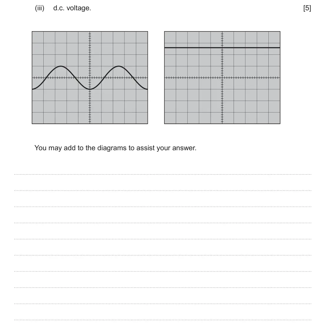
Q7(b)(i)
The whole paper ↗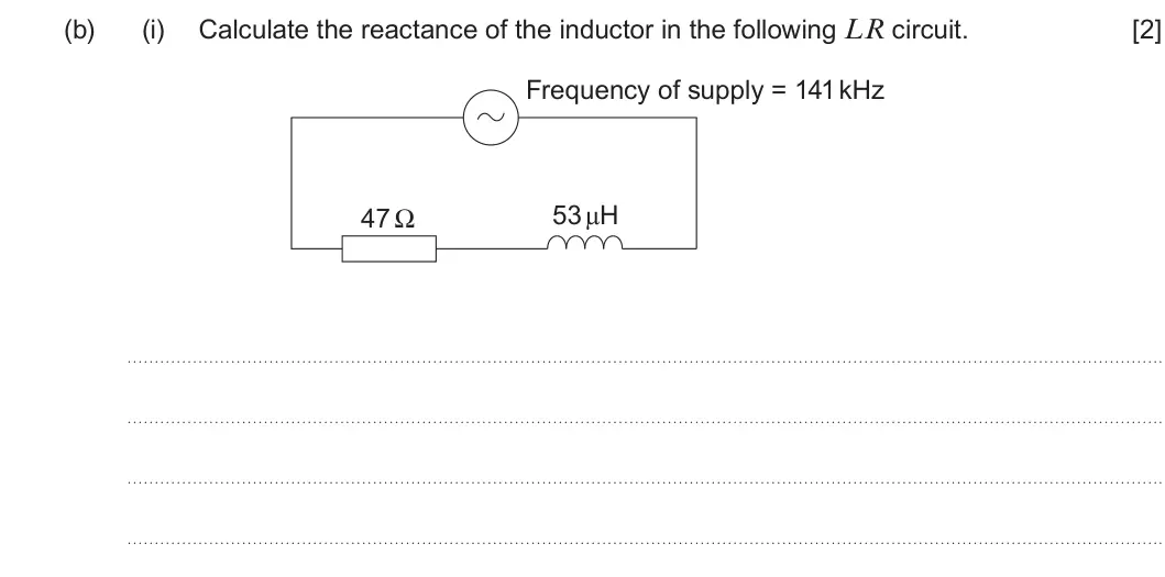
Q7(b)(ii)
The whole paper ↗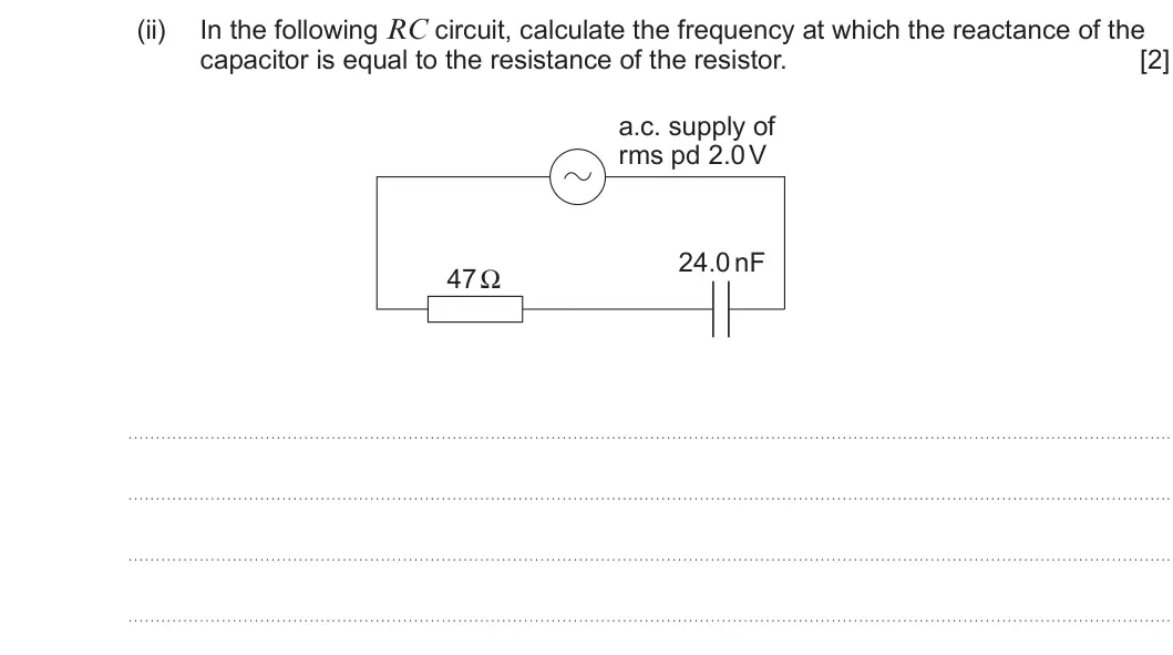
Q7(b)(iii)
The whole paper ↗
Q7(b)(iv)
The whole paper ↗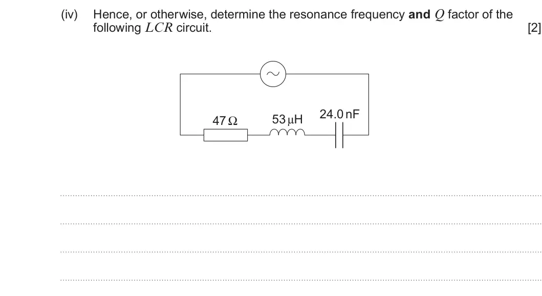
Q7(b)(v)
The whole paper ↗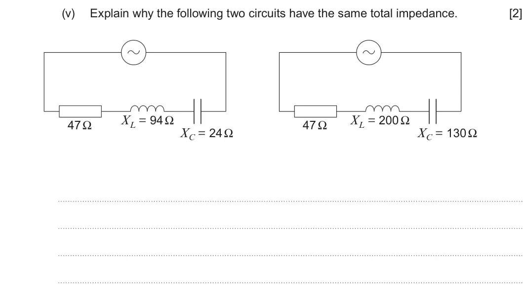
Q7(c)
The whole paper ↗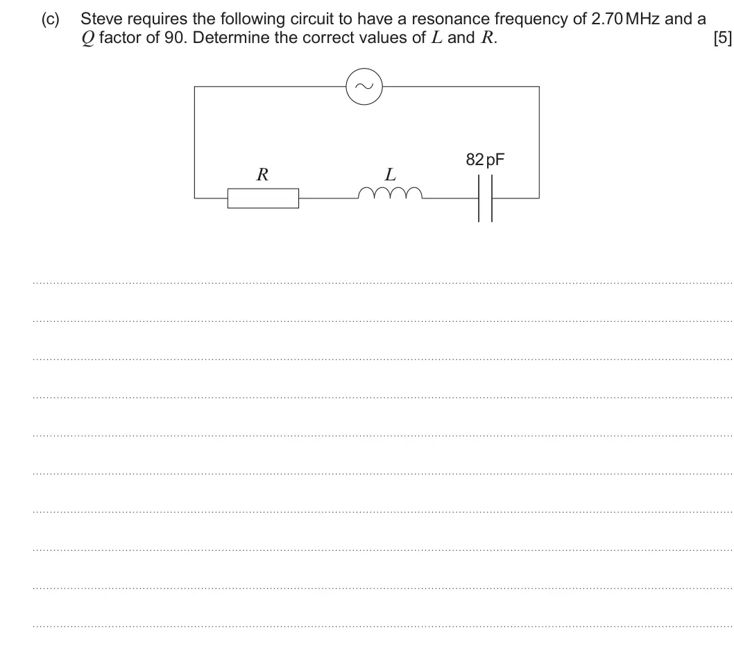
Q7(a)(i)
The whole paper ↗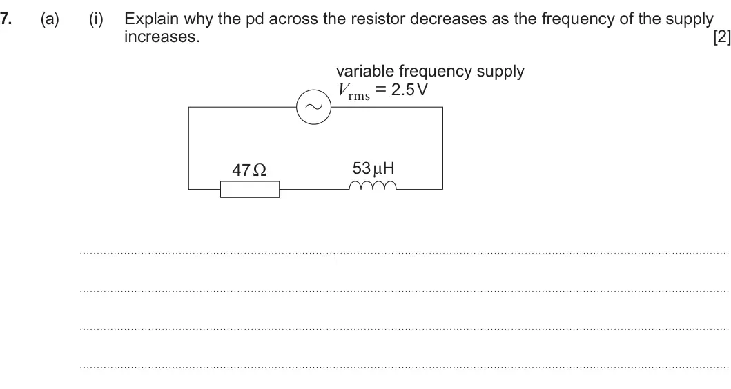
Q7(a)(ii)
The whole paper ↗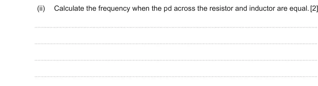
Q7(a)(iii)
The whole paper ↗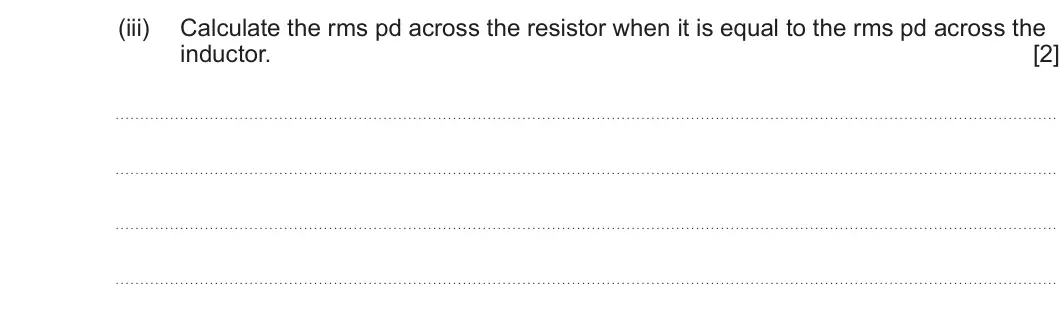
Q7(b)(i)
The whole paper ↗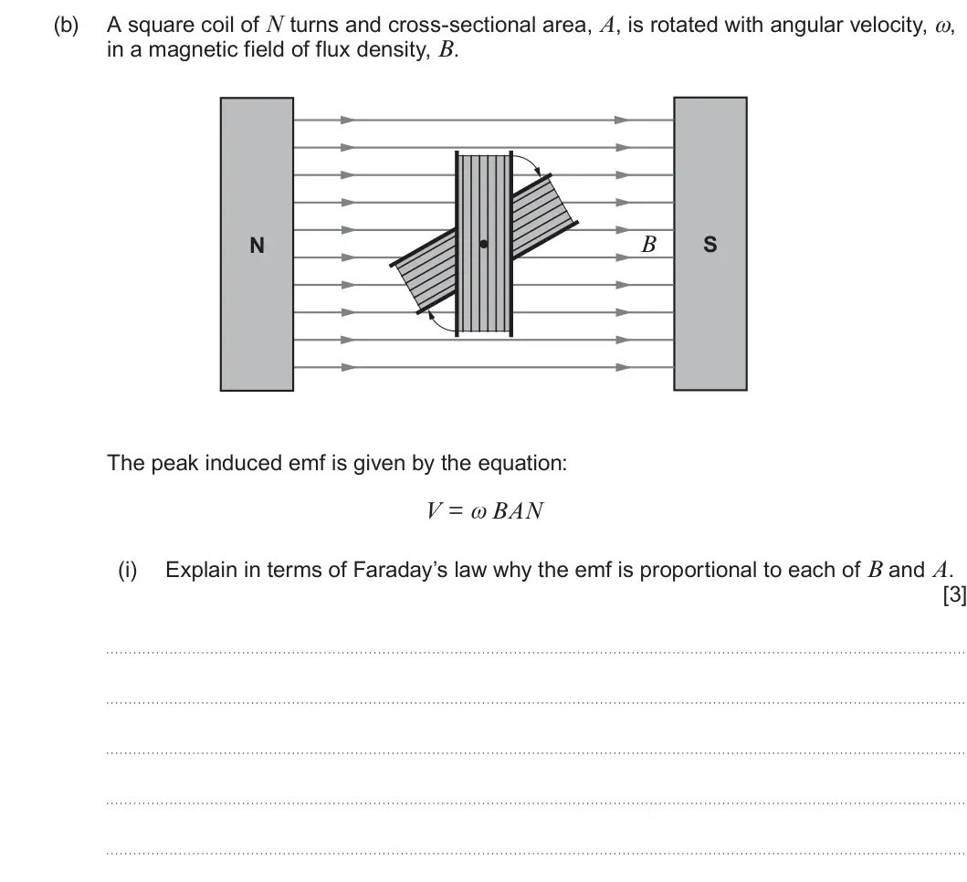
Q7(b)(ii)
The whole paper ↗
Q7(c)(i)
The whole paper ↗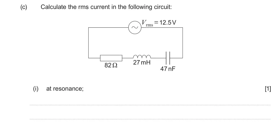
Q7(c)(ii)
The whole paper ↗
Q7(d)
The whole paper ↗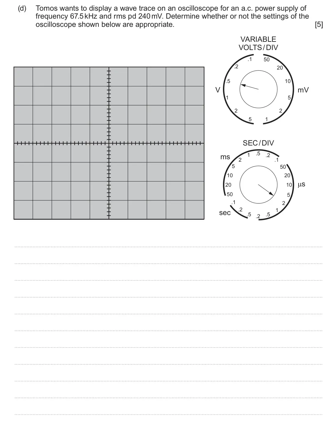
Q7(a)(i)
The whole paper ↗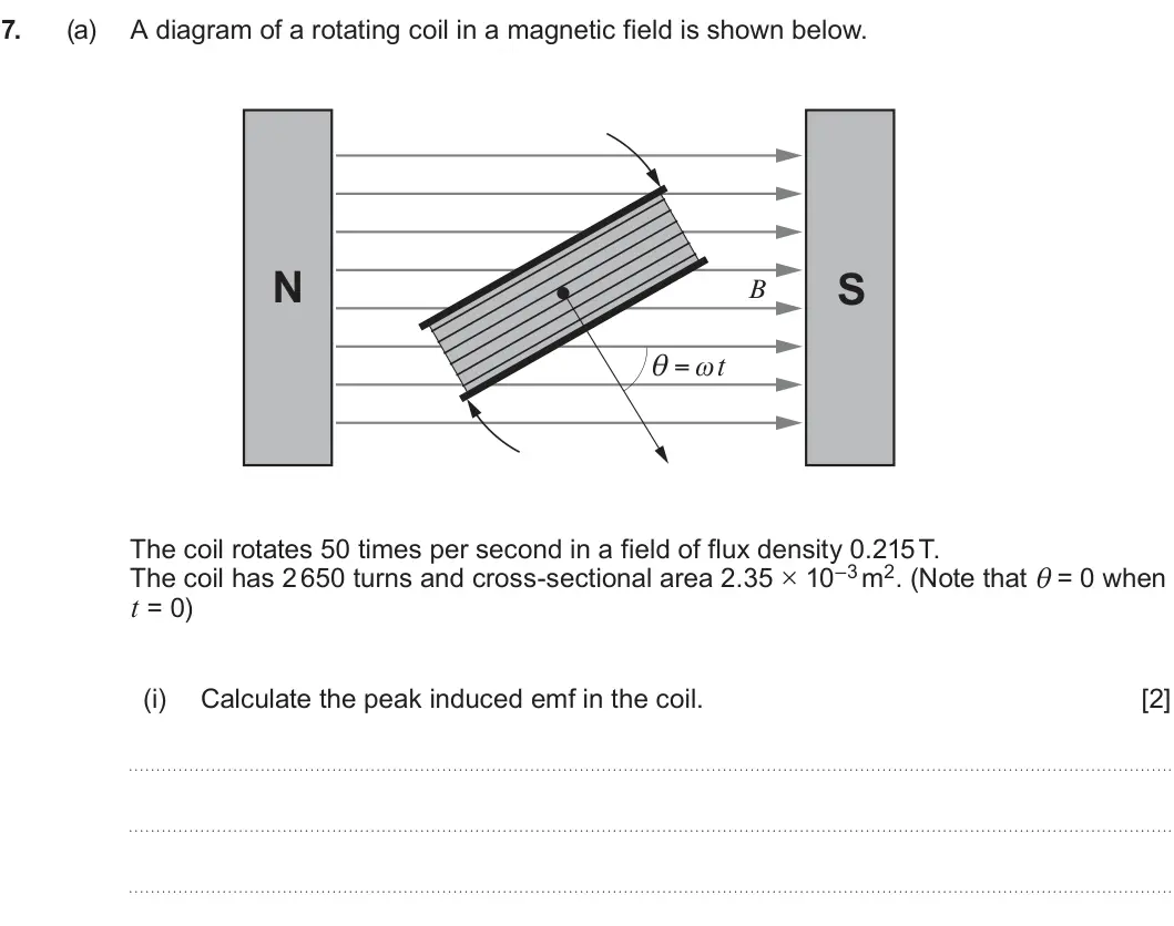
Q7(a)(ii)
The whole paper ↗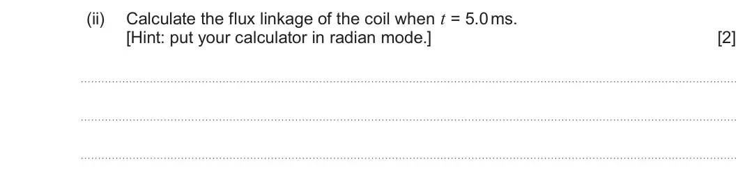
Q7(a)(iii)
The whole paper ↗
All 49 questions on Alternating currents, as a list
- Summer 2025, Unit 4, Q7(a)(i): peak a.c. voltage;
- Summer 2025, Unit 4, Q7(a)(ii): period of an a.c. supply;
- Summer 2025, Unit 4, Q7(a)(iii) (5 marks): d.c. voltage. [5] You may add to the diagrams to assist your answer.
- Summer 2025, Unit 4, Q7(b)(i) (2 marks): Calculate the reactance of the inductor in the following LR circuit. [2] Frequency of supply = 141 kHz 53 μH 47 Ω
- Summer 2025, Unit 4, Q7(b)(ii) (2 marks): In the following RC circuit, calculate the frequency at which the reactance of the capacitor is equal to the resistance of the resistor. [2] a.c. supply of rms
- Summer 2025, Unit 4, Q7(b)(iii) (2 marks): Calculate the rms pd across the resistor when this occurs. [2]
- Summer 2025, Unit 4, Q7(b)(iv) (2 marks): Hence, or otherwise, determine the resonance frequency and Q factor of the following LCR circuit. [2] 24.0 nF 53 μH 47 Ω
- Summer 2025, Unit 4, Q7(b)(v) (2 marks): Explain why the following two circuits have the same total impedance. [2] XL = 94 Ω XL = 200 Ω 47 Ω 47 Ω XC = 24 Ω XC = 130 Ω
- Summer 2025, Unit 4, Q7(c) (5 marks): Steve requires the following circuit to have a resonance frequency of 2.70 MHz and a Q factor of 90 Determine the correct values of L and R. [5] 82pF R L
- Summer 2024, Unit 4, Q7(a)(i) (2 marks): Explain why the pd across the resistor decreases as the frequency of the supply increases. [2] variable frequency supply Vrms = 2.5 V 53 μH 47 Ω
- Summer 2024, Unit 4, Q7(a)(ii) (2 marks): Calculate the frequency when the pd across the resistor and inductor are equal. [2]
- Summer 2024, Unit 4, Q7(a)(iii) (2 marks): Calculate the rms pd across the resistor when it is equal to the rms pd across the inductor. [2]
- Summer 2024, Unit 4, Q7(b)(i) (3 marks): Explain in terms of Faraday’s law why the emf is proportional to each of B and A. [3]
- Summer 2024, Unit 4, Q7(b)(ii) (1 mark): Explain at which point in the cycle the peak emf occurs. [1]
- Summer 2024, Unit 4, Q7(c)(i) (1 mark): at resonance; [1]
- Summer 2024, Unit 4, Q7(c)(ii) (4 marks): at twice the resonance frequency. [4]
- Summer 2024, Unit 4, Q7(d) (5 marks): Tomos wants to display a wave trace on an oscilloscope for an a.c. power supply of frequency 67.5 kHz and rms pd 240 mV. Determine whether or not the settings o
- Summer 2023, Unit 4, Q7(a)(i) (2 marks): Calculate the peak induced emf in the coil. [2]
- Summer 2023, Unit 4, Q7(a)(ii) (2 marks): Calculate the flux linkage of the coil when t = 5.0 ms. [Hint: put your calculator in radian mode.] [2]
- Summer 2023, Unit 4, Q7(a)(iii) (1 mark): Calculate the induced emf in the coil when t = 5.0 ms. [1]
- Summer 2023, Unit 4, Q7(a)(iv) (3 marks): Vanessa states that her answers to parts (ii) and (iii) are consistent with the coil having completed a quarter of a cycle. Determine whether or not she is corr
- Summer 2023, Unit 4, Q7(b)(i) (2 marks): Calculate the resonance frequency of the following circuit. [2] Vrms = 2.5 V C = 150 pF R = 180 Ω L = 16 mH
- Summer 2023, Unit 4, Q7(b)(ii) (2 marks): Explain why the rms current at resonance is approximately 14 mA. [2]
- Summer 2023, Unit 4, Q7(b)(iii) (4 marks): Calculate the rms current in the circuit when the frequency is 105 kHz. [4]
- Summer 2023, Unit 4, Q7(b)(iv) (2 marks): Explain why your answers to parts (b)(i), (b)(ii) and (b)(iii) suggest that the circuit has a high Q factor. [2]
- Summer 2023, Unit 4, Q7(b)(v) (2 marks): Thomas considers the effect, on this circuit, of increasing the capacitance only. He believes that this will decrease the Q factor. Determine whether or not he
- Summer 2019, Unit 4, Q6(a)(i) (3 marks): when the circuit is not in resonance; [3] Space for diagram.
- Summer 2019, Unit 4, Q6(a)(ii) (2 marks): when the circuit is in resonance. [2]
- Summer 2019, Unit 4, Q6(b)(i) (1 mark): the Q factor of the circuit; [1]
- Summer 2019, Unit 4, Q6(b)(ii) (1 mark): the rms current; [1]
- Summer 2019, Unit 4, Q6(b)(iii) (2 marks): the frequency of the power supply; [2]
- Summer 2019, Unit 4, Q6(b)(iv) (2 marks): the inductance of the inductor. [2]
- Summer 2019, Unit 4, Q6(b)(v) (2 marks): Sketch a graph of the instantaneous pd across the capacitor on the grid provided. (The instantaneous pd across the resistor is shown.) [2] Instantaneous pd / V
- Summer 2019, Unit 4, Q6(b)(vi) (2 marks): Without further calculation, explain why the current decreases when the frequency of the power supply is increased. [2]
- Summer 2019, Unit 4, Q6(c) (5 marks): Sam claims that the output pd (VOUT) in the following circuit is greater than 6.0 V when the frequency is greater than 20 kHz, but less than 6.0 V when below 20
- Summer 2018, Unit 4, Q6(a)(i) (2 marks): The output of the rotating coil is used to power a small lamp of known resistance. Explain how you would calculate the rms input power to the lamp from the know
- Summer 2018, Unit 4, Q6(a)(ii) (5 marks): Draw a typical trace that might be seen on the oscilloscope screen with the oscilloscope settings shown. [5] Space for calculations. VARIABLE VOLTS/DIV .1 50 .2
- Summer 2018, Unit 4, Q6(b)(i) (3 marks): Explain why the resonance frequency of the circuit occurs when: [3] 1 ω = L ω C
- Summer 2018, Unit 4, Q6(b)(ii) (2 marks): Calculate the resonance frequency of the circuit. [2]
- Summer 2018, Unit 4, Q6(b)(iii) (3 marks): Calculate the rms current when the frequency of the supply is 324 kHz. [3]
- Summer 2018, Unit 4, Q6(b)(iv) (5 marks): A student claims that the following circuit cannot have a peak pd above 1.5 kV across the capacitor. Investigate whether or not he is correct. [5] (It may be us
- Summer 2017, Unit 4, Q6(a)(i) (2 marks): Use Faraday’s law to explain why the emf is proportional to the angular velocity of the coil. [2] The peak emf induced in a rotating coil is given by: E = ωBAN
- Summer 2017, Unit 4, Q6(a)(ii) (3 marks): Discuss the agreement of the graph with the equation for the peak emf and suggest a reason for any disagreement (see diagram of coil opposite). [3]
- Summer 2017, Unit 4, Q6(b)(i) (2 marks): The minimum impedance of the circuit below occurs when the frequency of the a.c. supply is zero. Explain why this is so. [2] variable frequency a.c. supply Vrms
- Summer 2017, Unit 4, Q6(b)(ii) (3 marks): Calculate the rms current when the rms pd across the resistor and inductor are equal. [3]
- Summer 2017, Unit 4, Q6(c)(i) (3 marks): Explain how resonance arises in the LCR circuit shown. [3] variable frequency a.c. supply Vrms = 12 V 5.2 mH 82 Ω 220 nF
- Summer 2017, Unit 4, Q6(c)(ii) (2 marks): Calculate the power dissipated in the circuit at resonance. [2]
- Summer 2017, Unit 4, Q6(c)(iii) (3 marks): Calculate the rms current when the frequency of the supply is 9.40 kHz. [3]
- Summer 2017, Unit 4, Q6(c)(iv) (2 marks): Discuss briefly the effectiveness of the given LCR circuit for providing a sharp resonance curve. [2] ω0L R = 1 L (It may be useful to note that ) C . R
Questions, mark schemes and examiner’s reports are © WJEC CBAC Ltd, from their published past papers. Plumi isn’t affiliated with any exam board. Want whole papers? Every WJEC A-Level Physics paper.
Rather write your answers by hand on iPad? Plumi marks them against the same mark schemes.