 plumi
Capacitor charging and discharging: OCR A‑Level Physics B questions
OCR A-Level Physics B past-paper questions on 5.1.1.2 Capacitor charging and discharging, 2016–2025, with mark schemes and examiner’s reports where available.
Paper
All papers
Exam
All years
Calculations
Q32(b)
The whole paper ↗
- Your answer
- Your answer
- Your answer
Q3(a)
The whole paper ↗
Q3(b)(i)
The whole paper ↗Q3(b)(ii)
The whole paper ↗Q3(b)(iii)
The whole paper ↗Q3(c)(i)
The whole paper ↗Q3(c)(ii)
The whole paper ↗- Your answer
- Your answer
Q34(b)
The whole paper ↗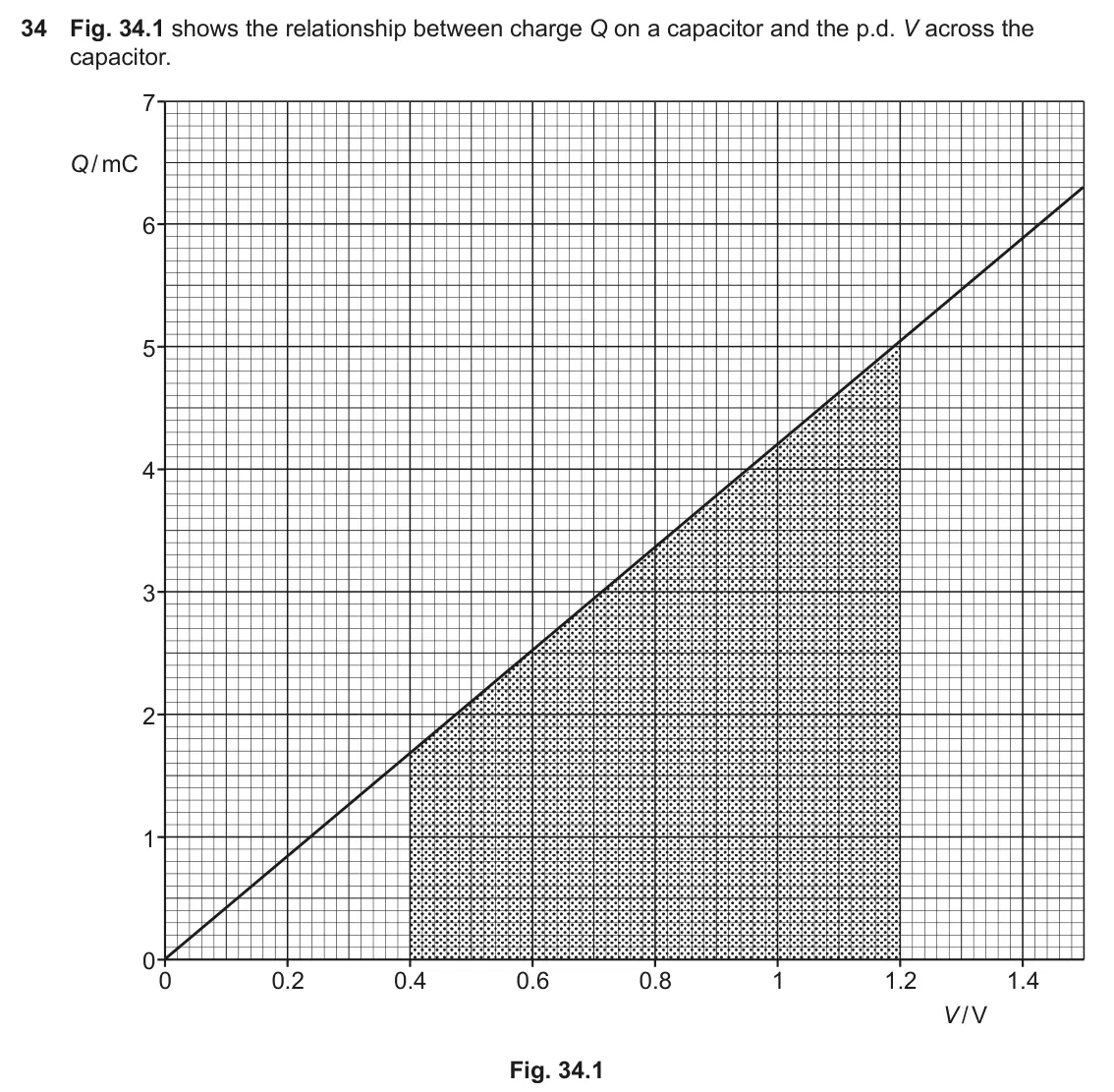
- Your answer
Q2(a)(i)
The whole paper ↗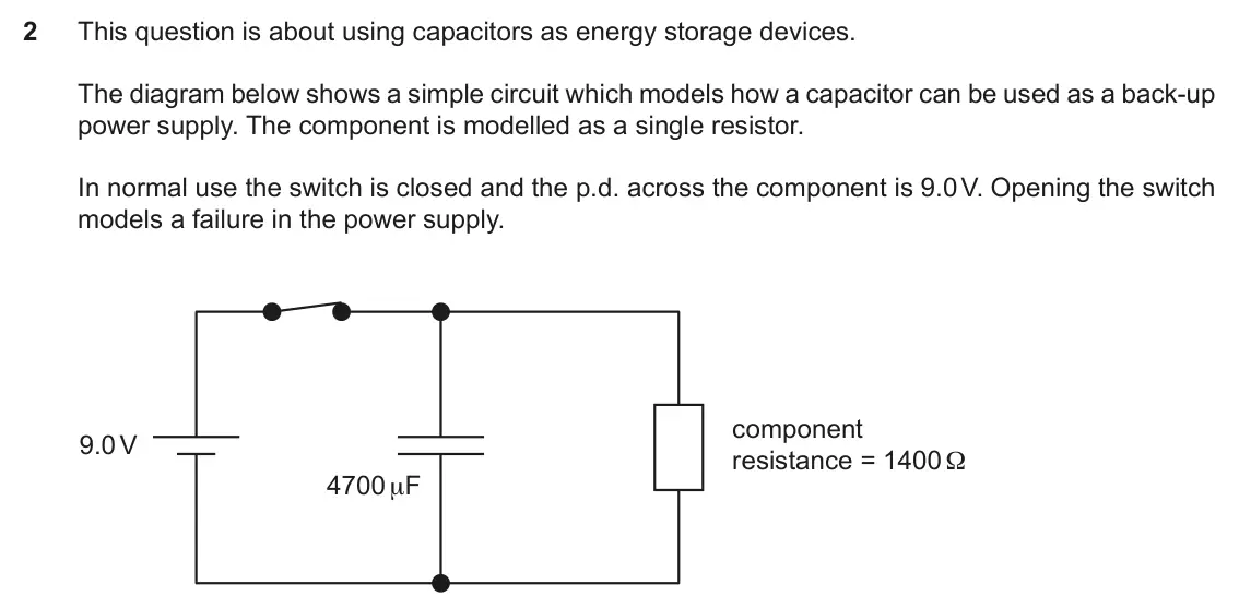
Q2(a)(ii)
The whole paper ↗Q2(b)
The whole paper ↗Q1(a)(i)
The whole paper ↗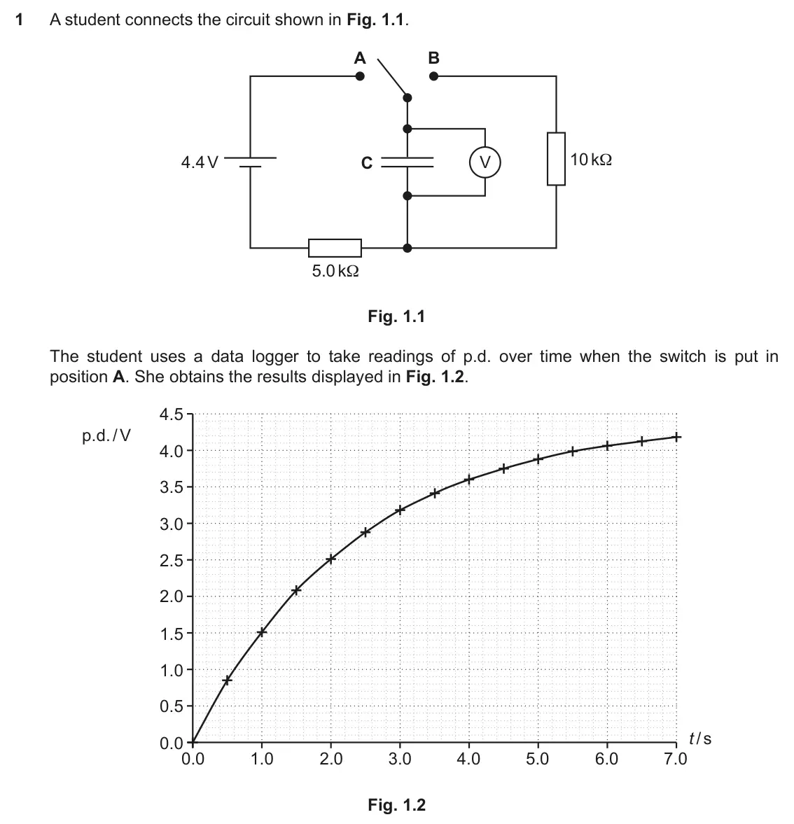
Q1(a)(ii)
The whole paper ↗Q1(b)(i)
The whole paper ↗
All 34 questions on Capacitor charging and discharging, as a list
- June 2025, Paper 1, Q32(b) (4 marks): A 680 μF capacitor is charged until it stores 12 mJ energy. It is then discharged through a 1.2 kΩ resistor. Calculate the time taken for the capacitor to trans
- June 2024, Paper 1, Q30 (1 mark): The capacitor in this circuit is initially uncharged. A V The graphs all show the variation of different quantities associated with the circuit after the switch
- June 2023, Paper 1, Q23 (1 mark): A 220 μF capacitor discharges through a resistor R. The p.d. across the capacitor falls to 20% of its original value after 5 seconds. What is the value of resis
- June 2023, Paper 1, Q24 (1 mark): A 4700 μF capacitor is connected across a 6.0 V supply as shown. It is discharged through a 6.0 kΩ resistor. 6.0 V 4700 μF 6.0 kΩ How long does it take, after t
- June 2023, Paper 3, Q3(a) (4 marks): You are provided with the following apparatus: variable power supply (0 – 12 V) capacitor of unknown capacitance resistor of value 4.7 kΩ multimeter leads and s
- June 2023, Paper 3, Q3(b)(i) (3 marks): Capacitor discharge is an example of exponential decay and follows the equation –t V = V0e RC. Complete the ln V column in Table 3 and then perform a mathematic
- June 2023, Paper 3, Q3(b)(ii) (1 mark): Show that the value of the time constant, τ is approximately 25 s. [1]
- June 2023, Paper 3, Q3(b)(iii) (1 mark): Calculate the value of the capacitance. Capacitance = F [1]
- June 2023, Paper 3, Q3(c)(i) (3 marks): Starting from the equation given in (b)(i) and repeated below show that when t = 5τ, the energy stored in the capacitor, E = 4.5 × 10⁻⁵ E0, where E0 is the ener
- June 2023, Paper 3, Q3(c)(ii) (1 mark): Justify why this rule of thumb is useful to engineers. [1]
- June 2022, Paper 1, Q27 (1 mark): The capacitor in the circuit shown is initially uncharged. At time t = 0 s, the switch is moved to position X. What is the potential difference across the capac
- June 2022, Paper 1, Q28 (1 mark): When the capacitor is fully charged, the switch is moved to position Y. What is the energy stored on the capacitor after 10 s of discharge? A 0.013 J B 0.023 J
- June 2022, Paper 1, Q34(b) (3 marks): A simplified circuit is shown in Fig. 34.2. C R Fig. 34.2 Explain how the equation ∆Q ∆t = – Q RC can be used to find the charge remaining on the capacitor afte
- November 2021, Paper 1, Q16 (1 mark): A charged capacitor discharges through a resistor with the time constant τ = RC. What is the best explanation of the time constant τ? A τ is the time for the ch
- November 2021, Paper 2, Q2(a)(i) (2 marks): The operating range of the component is 5.2 V to 9.0 V. Show that 3.5 s after the switch is opened the p.d. across the component will be about 5.3 V. [2]
- November 2021, Paper 2, Q2(a)(ii) (3 marks): Estimate the average power delivered to the component during this time. Explain why the value is an average. average power = W Explanation: [3] 5 In recent year
- November 2021, Paper 2, Q2(b) (4 marks): A 120 F supercapacitor has an internal resistance of 30 mΩ. At time t = 0.0 s it stores 300 J. Calculate the minimum time taken for the capacitor to transfer 25
- November 2020, Paper 2, Q1(a)(i) (1 mark): Suggest why the student chooses to use a data logger rather than a digital meter. [1]
- November 2020, Paper 2, Q1(a)(ii) (3 marks): Use data from the graph to show that the capacitance of C is about 500 μF. [3]
- November 2020, Paper 2, Q1(b)(i) (3 marks): When the capacitor is charged to 4.2 V, the student resets the data logger to t = 0.0 s and moves the switch from position A to position B. Draw a line on Fig.
- November 2020, Paper 2, Q1(b)(ii) (3 marks): Calculate the time from the beginning of the discharge for the energy stored on the capacitor to fall to half its value. time = s [3]
- June 2019, Paper 1, Q39(a)(i) (2 marks): Use the graph to find the initial current when the capacitor starts to charge. Make your method clear. initial current = A [2]
- June 2019, Paper 1, Q39(a)(ii) (2 marks): Calculate the size of the electrical resistance in the charging circuit. resistance = Ω [2]
- June 2019, Paper 1, Q39(b) (1 mark): Explain why the charging current decreases as the capacitor charges. [1]
- June 2019, Paper 1, Q39(c)(i) (2 marks): A student makes an iterative model for the charging of the capacitor in (a), using time intervals ∆t = 2.0 s. The start conditions and the situation at times t
- June 2019, Paper 1, Q39(c)(ii) (2 marks): Compare the model values for the charge Q on the capacitor at time t = 4.0 s with the experimental values from Fig. 39.1. Explain any differences and state how
- June 2018, Paper 1, Q13 (1 mark): Which set of values A to D above, most closely represents the situation immediately after the switch is closed? Your answer [1]
- June 2018, Paper 1, Q14 (1 mark): Which set of values A to D above, most closely represents the situation 3 seconds after the switch is closed? Your answer [1]
- June 2017, Paper 1, Q34(a) (2 marks): Complete the numerical values in the two blank cells in the table. [2]
- June 2017, Paper 1, Q34(b)(i) (2 marks): Explain the physics behind the approximation in the third column of the table Q . T . RC [2]
- June 2017, Paper 1, Q34(b)(ii) (2 marks): State the assumption made in using this approximation and explain how its effect can be made insignificant. [2]
- June 2017, Paper 2, Q2(b) (2 marks): A student changes the circuit as shown in Fig. 2.2 6.0 V 2.0 kΩ 4.7 kΩ 2200 μF Fig. 2.2 Show that the time constant of the circuit is about 15 s. [2]
- June 2017, Paper 2, Q2(c) (2 marks): The graph in Fig. 2.3 shows how the p.d. across the capacitor varies with time up to 5 RC. Add a line to the graph that shows how the p.d. across the 4.7 kΩ res
- June 2017, Paper 2, Q2(d) (4 marks): Calculate the time it takes from the start of the charging for the p.d across the capacitor to reach 5.0 V. time = s [4]
Questions, mark schemes and examiner’s reports are © OCR, from their published past papers. Plumi isn’t affiliated with any exam board. Want whole papers? OCR A-Level Physics B past papers.
The Plumi iPad app also offers exam-style questions with AI feedback on your handwritten working.