 plumi
Circuits: AQA A‑Level Physics questions
AQA A-Level Physics past-paper questions on 3.5.1.4 Circuits, 2008–2025, with mark schemes and examiner’s reports where available.
Paper
All papers
Exam
All years
Calculations
Q05.2
The whole paper ↗
Q02.5
The whole paper ↗
Q03.2
The whole paper ↗
Q03.3
The whole paper ↗Q03.4
The whole paper ↗Q06.2
The whole paper ↗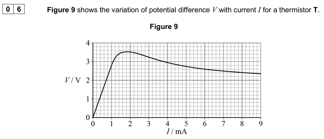
Q03.3
The whole paper ↗
Q03.4
The whole paper ↗Q06.1
The whole paper ↗
Q06.4
The whole paper ↗Q05.2
The whole paper ↗
Q05.3
The whole paper ↗Q05.4
The whole paper ↗
All 155 questions on Circuits, as a list
- June 2025, Paper 1, Q05.2 (2 marks): Figure 6 shows an array of 20 of these cells connected to form a module. Figure 6 Calculate the internal resistance of the module shown in Figure 6. [2 marks] i
- June 2025, Paper 1, Q28 (1 mark): In a circuit, the resistance of resistor R1 is double the resistance of resistor R2. The internal resistance of the battery is negligible. When the switch is op
- June 2025, Paper 3A, Q02.5 (3 marks): The student has access to a range of fixed and variable resistors. The student wants to modify the circuit in Figure 3 so that T can be varied continuously from
- June 2025, Paper 3A, Q03.2 (2 marks): Explain how the ammeter and voltmeter readings are used to determine values of P and T. [2 marks] P T
- June 2025, Paper 3A, Q03.3 (3 marks): Complete Table 2. [3 marks] Table 2 T / K P / W P1 / W P2 / W 960 3.7 1.2 2.5 1100 2.0 3.0 1370 1680 16.2 11.0
- June 2025, Paper 3A, Q03.4 (5 marks): It can be shown that P1∝T n where n is an integer. Determine n. In your answer you should: • use Table 3 to organise the data you will plot • plot a suitable gr
- June 2025, AS Paper 1, Q06.2 (3 marks): Figure 10 shows thermistor T in series with a fixed resistor R and a battery. The variation of V with I shown in Figure 9 applies to T in this circuit. Figure 1
- June 2025, AS Paper 2, Q03.3 (2 marks): Determine the resistance of X when it operates at a power of 65 W. [2 marks] resistance of X = Ω
- June 2025, AS Paper 2, Q03.4 (4 marks): The diameter of the filament of X decreases during use. This changes the resistance of X. The resistance of Y does not change. The emf and the internal resistan
- June 2025, AS Paper 2, Q26 (1 mark): The diagram shows the currents in a set of wires. What is the current in wire W? [1 mark] A 1 A B 2 A C 5 A D 7 A
- June 2025, AS Paper 2, Q30 (1 mark): A cell of negligible internal resistance is connected in parallel to a 20 Ω resistor and a resistor R. The emf of the cell is 6.0 V. The current in the cell is
- June 2025, AS Paper 2, Q33 (1 mark): A battery with negligible internal resistance is connected to a resistor of resistance 2.0 kΩ. The current in the battery is 6.0 mA. A non-ideal voltmeter is th
- June 2024, Paper 1, Q06.1 (2 marks): Calculate the resistance of the variable resistor. [2 marks] resistance = Ω
- June 2024, Paper 1, Q06.4 (2 marks): Explain how ammeters and voltmeters can be used in the circuit in Figure 5 to demonstrate the conservation of charge and the conservation of energy. Refer to po
- June 2024, AS Paper 1, Q05.2 (2 marks): Calculate the power dissipated in L1 when I is 1.9 A. [2 marks] power dissipated = W Question 5 continues on page 21
- June 2024, AS Paper 1, Q05.3 (2 marks): The variable resistor R in Figure 12 is adjusted until I is 1.5 A and V is 3.3 V. Calculate the resistance of R. [2 marks] resistance of R = Ω
- June 2024, AS Paper 1, Q05.4 (3 marks): Figure 15 shows a second lamp L2, identical to L1, connected to the circuit. Figure 15 R is adjusted so that the potential difference across L1 is again 3.3 V.
- June 2024, AS Paper 2, Q13 (1 mark): A current of 4.0 A in a resistor produces a power of 8.0 W. What is the potential difference across this resistor when the power is 32 W? [1 mark] A 2.0 V B 4.0
- June 2024, AS Paper 2, Q18 (1 mark): A circuit contains a battery and three identical resistors RX, RY and RZ. What is X Y power in R power in R ? [1 mark] A 0.25 B 0.5 C 2 D 4
- June 2024, AS Paper 2, Q27 (1 mark): The electric motor of a lift raises a load of 750 N at a constant speed. The load moves through a vertical distance of 3.0 m in 1.5 s. As the load is being rais
- June 2023, Paper 1, Q27 (1 mark): A box with four terminals is connected to a cell and two ammeters. The top left terminal is X. Each of the boxes A to D is connected into the circuit in turn. A
- June 2023, Paper 1, Q29 (1 mark): A resistor dissipates 100 W when connected across a 25 V supply with negligible internal resistance. The supply output is reduced to 20 V and the resistor is re
- June 2023, Paper 3A, Q02.4 (3 marks): Complete Table 2. [3 marks]
- June 2023, Paper 3A, Q02.5 (3 marks): Plot on Figure 6 a graph of P against V. You should use only the data in your completed Table 2. [3 marks] Figure 6
- June 2023, Paper 3A, Q02.6 (2 marks): L is connected to a 12 V power supply of negligible internal resistance. L then dissipates its rated power Pr . A second lamp, identical to L, is now connected
- June 2023, AS Paper 1, Q06.3 (3 marks): Determine the power output of one LED when the torch is on. [3 marks] power output = W
- June 2023, AS Paper 2, Q11 (1 mark): A cell with negligible internal resistance is connected to two resistors of resistance 4R and R. The currents I1, I2 and I3 in the circuit are shown. Which equa
- June 2023, AS Paper 2, Q18 (1 mark): A circuit contains a thermistor and a resistor in parallel. The internal resistance of the cell is negligible. The temperature of the thermistor is increased. T
- June 2023, AS Paper 2, Q21 (1 mark): X, Y and Z are three networks of resistors. Which gives the networks in order of largest total resistance to smallest total resistance? [1 mark] A X, Y, Z B Y,
- June 2023, AS Paper 2, Q28 (1 mark): Which row shows the resistance of an ideal ammeter and of an ideal voltmeter? [1 mark] Resistance of ammeter Resistance of voltmeter A zero zero B zero infinite
- June 2023, AS Paper 2, Q32 (1 mark): The diagram shows a circuit containing three resistors X, Y and Z. X and Y each have resistance R. Z has resistance 2R. What is power in ? power in X Z [1 mark]
- June 2022, Paper 1, Q04.1 (1 mark): Show that the resistance of the 6.2 V, 4.5 W lamp at its working potential difference (pd) is about 9 Ω. [1 mark]
- June 2022, Paper 1, Q04.4 (2 marks): Figure 8 shows the 5.0 m length of wire wrapped around a tube to make the variable resistor. Figure 8 Two plugs connect the variable resistor into the circuit.
- June 2022, Paper 1, Q04.5 (2 marks): The student now makes a different circuit by connecting the variable resistor in parallel with the lamp. The contact is returned to its original position on the
- June 2022, Paper 1, Q30 (1 mark): Which value of resistance cannot be made by combining three 10 Ω resistors? [1 mark] A 3.3 Ω B 6.7 Ω C 15 Ω D 25 Ω
- June 2022, AS Paper 1, Q08.1 (2 marks): Figure 12 shows the variable resistor being used to investigate the variation of current with voltage for a filament lamp. The normal operating voltage of the l
- June 2022, AS Paper 1, Q08.4 (2 marks): Figure 14 shows an alternative circuit used to investigate the variation of current with voltage for the lamp. Figure 14 The circuit components are the same as
- June 2022, AS Paper 1, Q08.5 (2 marks): Calculate the power transferred by the battery when P is at position Y. [2 marks] power = W
- June 2022, AS Paper 2, Q03.1 (2 marks): The battery is connected to a charger that maintains a constant potential difference of 5.0 V across the battery. It takes 2.6 hours for the battery to become f
- June 2022, AS Paper 2, Q32 (1 mark): The diagram shows the currents in part of a circuit. What is the potential difference between points P and Q? [1 mark] A 60 V B 70 V C 180 V D 270 V
- June 2022, AS Paper 2, Q33 (1 mark): The currents in the four wires obey the relationship I1 + I2 + I3 + I4 = 0 This relationship is an expression of the law of conservation of [1 mark] A charge. B
- November 2021, Paper 1, Q06.1 (2 marks): Show that the current in the sensor circuit when the LDR is not illuminated by the light beam is approximately 16 µA. [2 marks]
- November 2021, Paper 1, Q27 (1 mark): The battery in this circuit has an emf of 4.2 V and negligible internal resistance. What are the readings on the voltmeter when the switch is open (off) and whe
- November 2021, Paper 3A, Q02.5 (2 marks): Figure 5 shows a circuit with LR connected to a resistor of resistance R. Figure 5 The power supply has emf 6.10 V and negligible internal resistance. The curre
- November 2021, AS Paper 1, Q06.2 (2 marks): Figure 13 shows the battery connected into a circuit. Figure 13 The ammeter is ideal. The voltmeter is non-ideal and has a resistance R. The reading on the volt
- November 2021, AS Paper 1, Q06.3 (3 marks): Show that the resistance R of the voltmeter is approximately 300 Ω. [3 marks]
- November 2021, AS Paper 1, Q06.4 (2 marks): The voltmeter is now connected across the battery terminals. Calculate the power dissipated in the voltmeter. [2 marks] power = W
- November 2021, AS Paper 1, Q06.5 (2 marks): The voltmeter is now connected across the 640 Ω resistor as shown in Figure 14. Figure 14 The reading on the voltmeter is 2.10 V. When the voltmeter was connect
- November 2021, AS Paper 2, Q04.4 (4 marks): The motor is connected to a 110 V dc supply that has negligible internal resistance. The maximum operating current in the motor is 5.0 A. The efficiency of the
- November 2021, AS Paper 2, Q29 (1 mark): The diagram shows the currents in a set of wires. What is the magnitude of the current at X? [1 mark] A zero B 2 A C 3 A D 6 A
- November 2021, AS Paper 2, Q30 (1 mark): Resistors of resistance R, R and 3R are connected as shown. What is the resistance of the arrangement? [1 mark] A 3 7 R B 7 3 R C 5 6 R D 6 5 R
- November 2020, Paper 1, Q05.1 (1 mark): Show that the resistance of one of the lamps when it is operating at 12 V is about 100 Ω. [1 mark]
- November 2020, Paper 1, Q05.2 (2 marks): Initially the power supply is connected to the lamps using two short copper wires of negligible resistance. Calculate the current in the power supply. [2 marks]
- November 2020, Paper 1, Q05.4 (4 marks): The demonstration is intended to show that the lamps are significantly dimmer when connected using the long constantan wires than when using the short copper wi
- November 2020, Paper 1, Q11 (1 mark): What quantity is measured in kW h? [1 mark] A charge B current C energy D power
- November 2020, AS Paper 2, Q29 (1 mark): Which row shows the resistances of an ideal ammeter and an ideal voltmeter? [1 mark] Ideal ammeter Ideal voltmeter A infinite infinite B infinite zero C zero in
- November 2020, AS Paper 2, Q31 (1 mark): A filament lamp with resistance 12 Ω is operated at a power of 36 W. How much charge flows through the filament lamp during 15 minutes? [1 mark] A 26 C B 1.6 kC
- June 2019, Paper 1, Q23 (1 mark): The diagram shows part of a circuit and the currents in the circuit. What is the potential difference between point P and earth? [1 mark] A 60 V B 100 V C 120 V
- June 2019, Paper 1, Q25 (1 mark): Two cylindrical wires P and Q are of equal length and made of the same material. The diameter of P is greater than that of Q. P and Q are connected in series an
- June 2019, Paper 3 Electronics, Q01.4 (3 marks): The potential difference across the green LED is 2.1 V when it is lit. The current through it should not exceed 9 mA. All logic gate outputs are: logic low = 0
- June 2019, AS Paper 1, Q02.3 (4 marks): A light emitting diode (LED) is used to indicate that the switch in the glove is closed, as shown in Figure 1. Resistor R limits the current in the LED. Figure
- June 2019, AS Paper 2, Q02.4 (4 marks): One of the circuits A to D shown in Figure 4 was used to obtain the current–voltage data in Figure 3. The maximum resistance of resistor P is twice the resistan
- June 2019, AS Paper 2, Q04.3 (3 marks): Either of the circuits shown in Figure 10a and Figure 10b could be used to reduce the initial current surge. Figure 10a Figure 10b The thermistor and the fixed
- June 2019, AS Paper 2, Q32 (1 mark): Resistors X and Y are connected in series with a 6.0 V battery of negligible internal resistance. X has resistance R and Y has resistance R 2 . A voltmeter of r
- June 2019, AS Paper 2, Q34 (1 mark): In the circuit shown, a potential difference of 3.0 V is applied across XY. What is the current in the 5 Ω resistor? [1 mark] A 0.38 A B 0.60 A C 0.75 A D 2.7 A
- June 2018, Paper 1, Q27 (1 mark): The two resistors shown are both uniform cylinders of equal length made from the same conducting putty. The diameter of Y is twice that of X. The resistance of
- June 2018, AS Paper 1, Q06.1 (4 marks): Table 1 shows the operating conditions for the lamps when they are at normal brightness. Table 1 Lamps Operating voltage / V Power / W A and C 6.0 6.0 B and D 3
- June 2018, AS Paper 1, Q06.2 (3 marks): The student connects another lamp E in the circuit as shown in Figure 7. Lamp E is identical to lamps A and C. Figure 7 Explain what the student would observe r
- June 2018, AS Paper 1, Q06.3 (3 marks): Lamp B in Figure 7 fails so that it no longer conducts. This change does not affect the resistance of the other lamps. Deduce the effect on the current in the b
- June 2018, AS Paper 2, Q03.5 (3 marks): The radioactive source was positioned 10 cm above the wire gauze before being moved slowly towards the wire gauze leading to the ionisation event in question 03
- June 2018, AS Paper 2, Q31 (1 mark): A circuit consists of a cell, a thermistor, a fixed resistor and two ammeters. The cell has a constant electromotive force and negligible internal resistance. R
- June 2018, AS Paper 2, Q32 (1 mark): A circuit consists of two identical cells, a resistor, an ammeter and a voltmeter. The cells each have an emf of 3.0 V and the resistor has a resistance of 12 Ω
- June 2018, AS Paper 2, Q34 (1 mark): The circuit shows a cell with negligible internal resistance connected in a circuit with three resistors, an ammeter and a voltmeter. Which row shows the readin
- June 2017, Paper 1, Q25 (1 mark): In the circuit below, the potential difference across the light emitting diode (LED) is 1.8 V when it is emitting light. The current in the circuit is 20 mA. Wh
- June 2017, Paper 1, Q26 (1 mark): The combined resistance of n identical resistors connected in parallel is Rn. Which statement correctly describes the variation of Rn as n increases? [1 mark] A
- June 2017, Paper 1, Q27 (1 mark): The table shows the resistivity, length and cross-sectional area of wires P and Q. resistivity length cross-sectional area wire P ρ L A wire Q 4 L 2 A The resis
- June 2017, Paper 1, Q29 (1 mark): In this resistor network, the emf of the supply is 12 V and it has negligible internal resistance. What is the reading on a voltmeter connected between points X
- June 2017, AS Paper 1, Q02.3 (3 marks): The resistor and the filament lamp are connected in series with a supply of variable emf and negligible internal resistance. Determine the emf that produces a c
- June 2017, AS Paper 1, Q02.4 (3 marks): The resistor and filament lamp are now connected in parallel. Determine the resistance of the parallel combination when the emf of the supply is adjusted to be
- June 2017, AS Paper 2, Q01.1 (1 mark): Calculate the largest value of R that the student can obtain using two resistors. [1 mark] largest value of R = Ω
- June 2017, AS Paper 2, Q01.2 (2 marks): Calculate the smallest value of R that the student can obtain using two resistors. [2 marks] smallest value of R = Ω
- June 2017, AS Paper 2, Q01.8 (2 marks): Figure 4 shows a different method for varying the resistance R described in question 01 on page 2. Figure 4 The four resistors are connected in a loop with sock
- June 2017, AS Paper 2, Q12 (1 mark): The current in the cell is 10 A as shown. What is the current in the 2.0 Ω resistor? [1 mark] A 0.35 A B 2.86 A C 3.50 A D 7.14 A
- June 2016, AS Paper 1, Q04.2 (1 mark): In order to measure the resistance of a used working probe, it is connected in the circuit shown in Figure 7. When R3 is adjusted to a particular value the curr
- June 2016, AS Paper 1, Q04.3 (1 mark): The resistance of R2 is 22 Ω and the resistance of R3 is 1.2 Ω. Calculate the current in R3. [1 mark] current = ____________________ A
- June 2016, AS Paper 1, Q04.4 (3 marks): Calculate the resistance of the probe when the resistance of R1 is 2.4 Ω. [3 marks] resistance = ____________________ Ω
- June 2016, AS Paper 2, Q04.4 (2 marks): Calculate the maximum number of components, each of resistance 45 Ω, that can be connected in parallel across the RTG before the maximum output power is reached
- June 2016, AS Paper 2, Q30 (1 mark): A cell C of negligible resistance and a switch are in series with a resistor R. The switch is moved to the on (closed) position for a time t. Which change reduc
- Specimen, Paper 1, Q03.1 (1 mark): The cells in the circuit shown in Figure 2 have zero internal resistance. Currents are in the directions shown by the arrows. Figure 2 R1 is a variable resistor
- Specimen, Paper 1, Q03.2 (1 mark): The cells in the circuit shown in Figure 2 have zero internal resistance. Currents are in the directions shown by the arrows. Figure 2 R1 is a variable resistor
- Specimen, Paper 1, Q03.3 (2 marks): The cells in the circuit shown in Figure 2 have zero internal resistance. Currents are in the directions shown by the arrows. Figure 2 R1 is a variable resistor
- Specimen, Paper 1, Q03.4 (3 marks): The cells in the circuit shown in Figure 2 have zero internal resistance. Currents are in the directions shown by the arrows. Figure 2 R1 is a variable resistor
- Specimen, Paper 1, Q15 (1 mark): In the circuit shown in the diagram the cell has negligible internal resistance. What happens to the reading of both meters when the resistance of R is decrease
- June 2016, PHYA1 (old spec), Q6(b)(i) (2 marks): Explain why the rms voltage across the heating element in the oven will be less than 230 V. [2 marks] __________________________________________________________
- June 2016, PHYA1 (old spec), Q6(b)(ii) (3 marks): Calculate the rms voltage across the heating element in the oven when it is at its working temperature. [3 marks] rms voltage = ___________________________ V
- June 2015, PHYA1 (old spec), Q5(c) (2 marks): Three identical filament lamps, P, Q and R are connected in the circuit shown in Figure 2. Figure 2 The filament in lamp Q melts so that it no longer conducts.
- June 2015, PHYA1 (old spec), Q7(b) (3 marks): Explain why only a small percentage of the total current in the cable passes through the steel wire. [3 marks]
- June 2015, PHYA1 (old spec), Q7(c) (3 marks): The potential difference across a length of 1.0 km of the cable is 75 V. Calculate the total power loss for a 1.0 km length of cable. [3 marks] Total power loss
- June 2013, PHYA1 (old spec), Q6(a)(ii) (1 mark): Calculate the pd across the 2.0Ω resistor. pd V (1 mark)
- June 2013, PHYA1 (old spec), Q6(a)(iii) (1 mark): Calculate the current in the 2.0Ω resistor. current A (1 mark)
- June 2013, PHYA1 (old spec), Q6(a)(iv) (1 mark): Determine the current in R. current A (1 mark)
- June 2013, PHYA1 (old spec), Q6(a)(v) (1 mark): Calculate the resistance of R. R Ω (1 mark)
- June 2013, PHYA1 (old spec), Q6(a)(vi) (2 marks): Calculate the total resistance of the circuit. circuit resistance Ω (2 marks)
- January 2013, PHYA1 (old spec), Q6(a)(i) (3 marks): calculate the total resistance of the circuit, total resistance = kΩ (3 marks)
- January 2013, PHYA1 (old spec), Q6(a)(ii) (1 mark): calculate the current in the battery. current = mA (1 mark)
- January 2013, PHYA1 (old spec), Q6(b) (3 marks): A high-resistance voltmeter is used to measure the potential difference (pd) between points A–C, D–F and C–D in turn. Complete the following table indicating th
- January 2013, PHYA1 (old spec), Q7(b)(ii) (1 mark): Calculate the pd across each of the wires. pd = V (1 mark)
- January 2013, PHYA1 (old spec), Q7(b)(iii) (2 marks): Calculate the emf (electromotive force) of the power supply. emf = V (2 marks)
- June 2012, PHYA1 (old spec), Q6(a)(i) (2 marks): Calculate the current in the battery. answer = A (2 marks)
- June 2012, PHYA1 (old spec), Q6(c)(i) (2 marks): Explain why the lamps will not be at their normal brightness in this circuit. (2 marks)
- June 2012, PHYA1 (old spec), Q6(c)(ii) (3 marks): State and explain which of the lamps will be brighter assuming that the resistance of the lamps does not change significantly with temperature. (3 marks) Turn t
- June 2012, PHYA1 (old spec), Q7(a)(i) (2 marks): Calculate the current in the circuit. answer = A (2 marks)
- June 2012, PHYA1 (old spec), Q7(a)(ii) (1 mark): Calculate the resistance of R1. answer = Ω (1 mark)
- January 2012, PHYA1 (old spec), Q6(b)(i) (1 mark): Calculate the pd across R1. answer V (1 mark)
- January 2012, PHYA1 (old spec), Q6(b)(ii) (1 mark): Calculate the current in R1. answer A (1 mark)
- January 2012, PHYA1 (old spec), Q6(b)(iii) (1 mark): Calculate the resistance of R1. answer Ω (1 mark)
- January 2012, PHYA1 (old spec), Q6(b)(iv) (1 mark): Calculate the pd across R2. answer V (1 mark)
- January 2012, PHYA1 (old spec), Q6(b)(v) (1 mark): Calculate the resistance of R2. answer Ω (1 mark)
- January 2012, PHYA1 (old spec), Q6(c)(i) (2 marks): Explain without calculation why the voltmeter reading decreases. (2 marks)
- January 2012, PHYA1 (old spec), Q6(c)(ii) (2 marks): Explain without calculation why the lamp Y glows more brightly. (2 marks)
- June 2011, PHYA1 (old spec), Q7(a)(i) (1 mark): Calculate the total resistance of the circuit. answer = Ω (1 mark)
- June 2011, PHYA1 (old spec), Q7(a)(ii) (3 marks): The resistors W, X, Y, and Z all have the same resistance. Show that your answer to part (a) (i) is consistent with the resistance of each resistor being 3.0Ω.
- June 2011, PHYA1 (old spec), Q7(b)(i) (2 marks): Calculate the current through resistor Y. answer = A (2 marks)
- June 2011, PHYA1 (old spec), Q7(b)(ii) (2 marks): Copyright © 2011 AQA and its licensors. All rights reserved. 7 (b) (ii) Calculate the pd across resistor W. answer = V (2 marks)
- January 2011, PHYA1 (old spec), Q6(d)(i) (2 marks): in series, (2 marks)
- January 2011, PHYA1 (old spec), Q6(d)(ii) (2 marks): in parallel. (2 marks)
- January 2011, PHYA1 (old spec), Q7(a)(i) (1 mark): Calculate the pd across the 540 Ω resistor. answer = V (1 mark)
- January 2011, PHYA1 (old spec), Q7(a)(ii) (1 mark): Calculate the pd across the 1200 Ω resistor. answer = V (1 mark)
- January 2011, PHYA1 (old spec), Q7(a)(iii) (2 marks): Calculate the resistance of the parallel combination of the resistor and the thermistor. answer = Ω (2 marks)
- January 2011, PHYA1 (old spec), Q7(a)(iv) (2 marks): Calculate the resistance of the thermistor. answer = Ω (2 marks)
- June 2010, PHYA1 (old spec), Q5(b)(ii) (1 mark): Calculate the current in the circuit. answer = A (1 mark)
- June 2010, PHYA1 (old spec), Q5(b)(iii) (2 marks): Calculate the resistance of R quoting your answer to an appropriate number of significant figures. answer = Ω (2 marks)
- January 2010, PHYA4 Section B (old spec), Q4(b)(i) (1 mark): Calculate the power wasted in the internal circuits when the TV set is left in standby mode. answer = W (1 mark)
- January 2010, PHYA4 Section B (old spec), Q4(b)(iii) (1 mark): The TV set is left in standby mode for 80% of the time. Calculate the amount of energy, in J, that is wasted in one year through the use of the standby mode. 1
- January 2010, PHYA4 Section B (old spec), Q4(b)(iv) (2 marks): Show that the cost of this wasted energy will be about £4, if electrical energy is charged at 20p per kWh. (2 marks)
- January 2010, PHYA1 (old spec), Q6(a)(i) (1 mark): Calculate the total resistance of the circuit. answer = Ω (1 mark)
- January 2010, PHYA1 (old spec), Q6(a)(ii) (1 mark): Calculate the total emf of the combination of cells. answer = V (1 mark)
- January 2010, PHYA1 (old spec), Q6(a)(iii) (2 marks): Calculate the current passing through cell A. answer = A (2 marks)
- January 2010, PHYA1 (old spec), Q6(b) (3 marks): Each of the cells can provide the same amount of electrical energy before going flat. State and explain which two cells in this circuit you would expect to go f
- June 2009, PHYA1 (old spec), Q5(b)(i) (2 marks): Calculate the current in the 8.0 Ω resistor answer A (2 marks)
- June 2009, PHYA1 (old spec), Q5(b)(ii) (3 marks): Calculate the current in the 4.0 Ω resistor if the p.d. across the diode, when in forward bias, is 0.65 V expressing your answer to an appropriate number of sig
- January 2009, PHYA1 (old spec), Q6(a) (2 marks): Calculate the total resistance between terminals A and B. answer = Ω (2 marks)
- January 2009, PHYA1 (old spec), Q6(b) (6 marks): A potential difference is applied between the two terminals, A and B, and the power dissipated in each of the 400 Ω resistors is 1.0 W. 6 (b) (i) Calculate the
- January 2009, PHA3W (2008 spec), Q2(a) (5 marks): 2 (a) (i) Calculate the total circuit resistance. 2 (a) (ii) Show that the potential difference across each resistor is 6.0 V. (5 marks)
- January 2009, PHA3W (2008 spec), Q2(b) (2 marks): 2 (b) Explain, without further calculation, why the power supplied to the 20 Ω resistor is the same as the power supplied to the parallel combination of the 30
- January 2009, PHA3W (2008 spec), Q3(a) (3 marks): 3 (a) (i) Calculate the peak voltage of the mains supply. 3 (a) (ii) Calculate the rms current supplied to the cooker when it is operating at full power. (3 mar
- January 2009, PHA3W (2008 spec), Q3(b) (6 marks): 3 (b) The cooker is connected permanently to the ac mains electricity supply using its own connecting cable of length 5.2 m. Each metre of the connecting cable
- January 2009, PHA3W (2008 spec), Q4(a) (4 marks): 4 (a) (i) Calculate the resistance of the thermistor at this temperature. 4 (a) (ii) Calculate the resistance of R. (4 marks)
- June 2008, PHA3W (2008 spec), Q1(a) (1 mark): 1 (a) Each lamp is rated at 2.0 W at a voltage of 8.0 V. Calculate the resistance of a lamp at this voltage. (1 mark)
- June 2008, PHA3W (2008 spec), Q1(b) (3 marks): 1 (b) The resistance of R is chosen so that the lamps are to operate at their normal working voltage of 8.0 V. Calculate 1 (b) (i) the current supplied by the b
- June 2008, PHA3W (2008 spec), Q1(c) (3 marks): 1 (c) When the lamps are at their correct working voltage, 1 (c) (i) calculate the time taken for a charge of 20 C to pass through one of the lamps, 1 (c) (ii)
- June 2008, PHA9W (2008 spec), Q5(c) (2 marks): 5 (c) When the red LED is on, the voltage across it is 1.6 V. 5 (c) (i) Calculate the current through its 500 Ω current limiting resistor. 5 (c) (ii) The 500 Ω
- January 2008, PHA3W (2008 spec), Q1(a) (5 marks): 1 (a) (i) A cable of length 8.0 m consists of a single strand of copper wire of cross-sectional area 7.8 × 10 –7 m 2. When the current through the cable is 5.0
- January 2008, PHA3W (2008 spec), Q2(a) (6 marks): 2 (a) A battery of emf 21 V and negligible internal resistance is connected to a resistor network as shown in Figure 1. Figure 1 21 V 80 Ω 20 Ω 15 Ω 60 Ω 40 Ω A
- January 2008, PHA3W (2008 spec), Q2(b) (4 marks): (b) A student is provided with the circuit shown in Figure 2, where P and Q are sealed boxes. Figure 2 The student is told that ! each of the boxes P and Q cont
Questions, mark schemes and examiner’s reports are © AQA, from their published past papers. Plumi isn’t affiliated with any exam board. Want whole papers? AQA A-Level Physics past papers.
The Plumi iPad app also offers exam-style questions with AI feedback on your handwritten working.