 plumi
Potential divider: AQA A‑Level Physics questions
AQA A-Level Physics past-paper questions on 3.5.1.5 Potential divider, 2008–2025, with mark schemes and examiner’s reports where available.
Paper
All papers
Exam
All years
Calculations
- Your answer
Q03.3
The whole paper ↗Q03.4
The whole paper ↗Q02.3
The whole paper ↗
Q02.1
The whole paper ↗
Q02.2
The whole paper ↗Q08.6
The whole paper ↗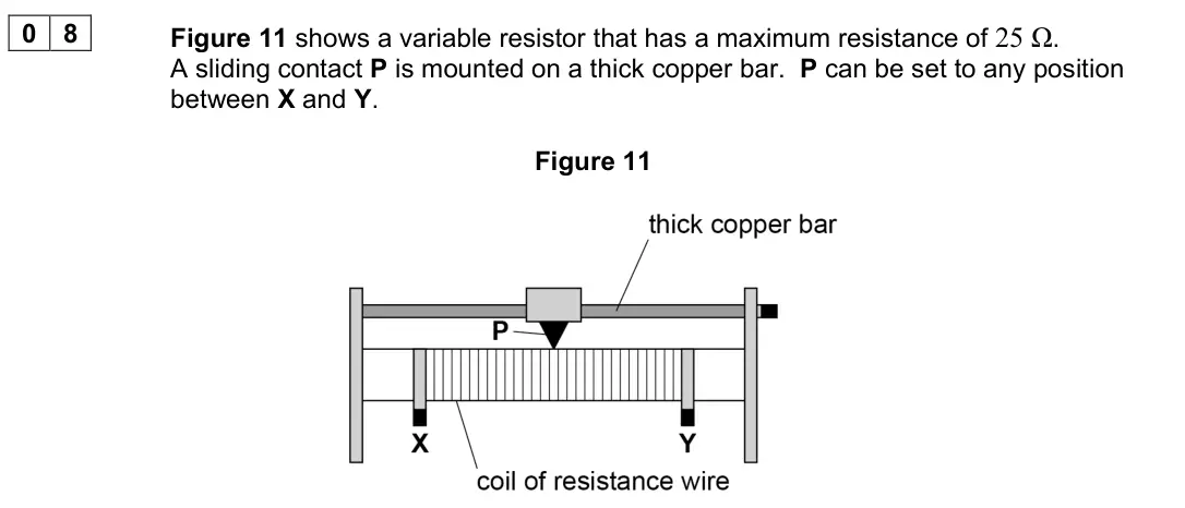
Q02.2
The whole paper ↗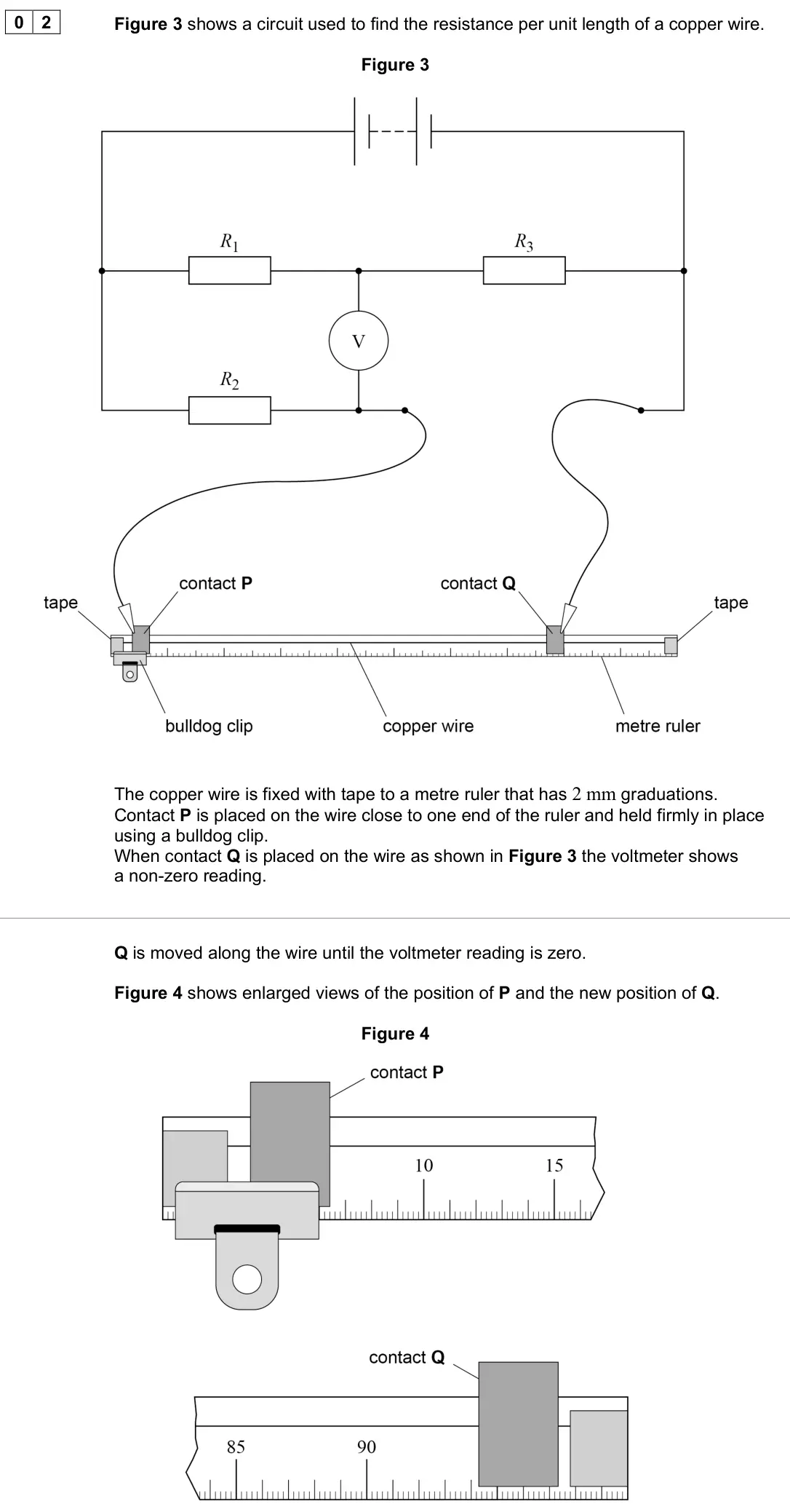
Q02.5
The whole paper ↗Q06.2
The whole paper ↗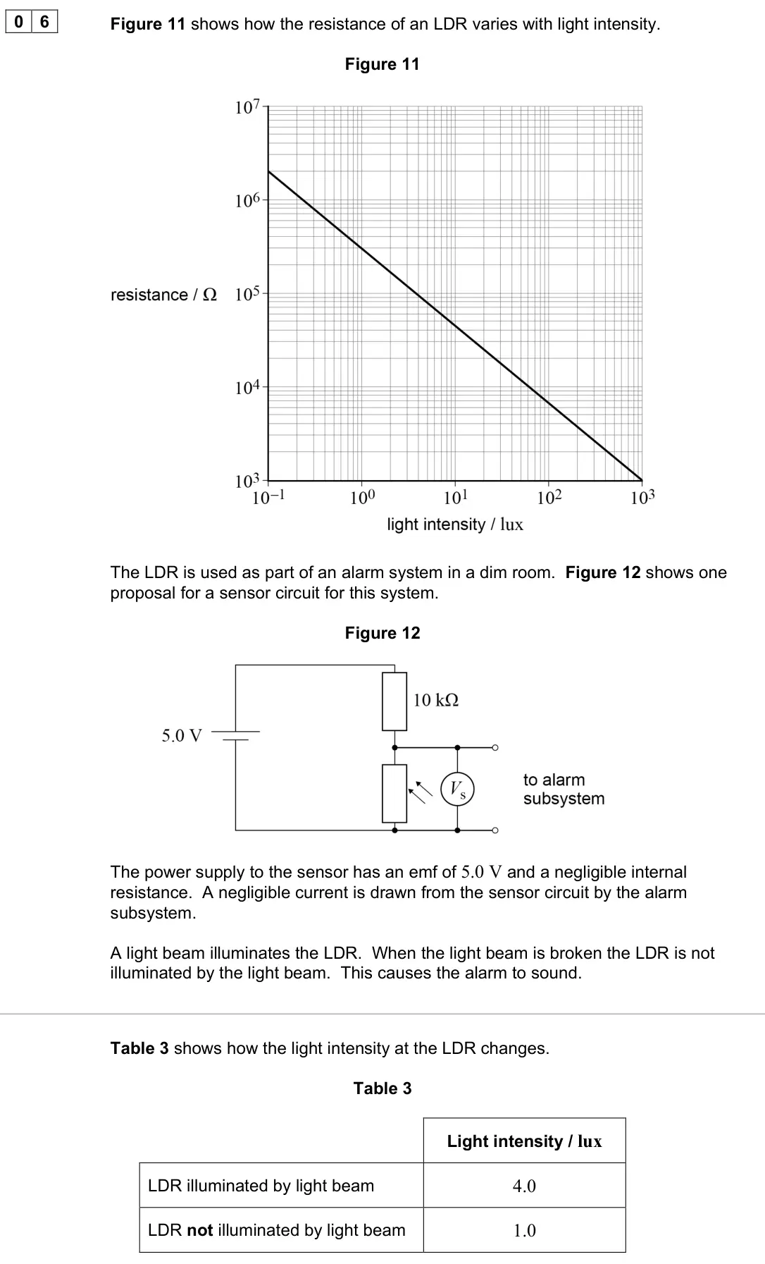
Q04.3
The whole paper ↗
- Your answer
All 47 questions on Potential divider, as a list
- June 2025, AS Paper 2, Q07 (1 mark): A long uniform metal wire XY is connected in parallel to two resistors M and N as shown. An ammeter connects the wire between M and N to a point P on XY. The re
- June 2024, AS Paper 2, Q09 (1 mark): A circuit contains a battery with an emf of 12 V and negligible internal resistance. At a certain light intensity, the LDR has a resistance of 480 Ω and the vol
- June 2024, AS Paper 2, Q26 (1 mark): A resistance wire XY of length 25 cm has constant cross-section. The wire is connected to a battery of emf 6.0 V and negligible internal resistance. What is the
- June 2023, Paper 1, Q03.3 (2 marks): C is set at 1 5 of the distance between A and B. The thickness of the conducting layer is uniform so the resistance between A and C is 25.0 Ω. Determine the vol
- June 2023, Paper 1, Q03.4 (4 marks): Figure 5 shows a variable resistor similar to the one shown in Figure 3 but with the following three manufacturing faults: • at P the conducting layer changes i
- June 2023, Paper 3A, Q02.3 (4 marks): Figure 5 shows two circuits that can be used to collect current–voltage data. Figure 5 The dc supply has an emf of 12 V and negligible internal resistance. The
- June 2023, Paper 3 Electronics, Q02.1 (3 marks): Figure 5 shows a circuit that contains two identical strain gauges A and B. The resistance of each strain gauge is 120.00 Ω when the strain is zero. R1 is a 560
- June 2023, Paper 3 Electronics, Q02.2 (2 marks): Explain the advantage of using strain gauge B rather than a 120.00 Ω resistor in the circuit. [2 marks]
- June 2023, AS Paper 2, Q30 (1 mark): Three resistors are connected in series with a 9.0 V battery of negligible internal resistance. The resistance of the variable resistor is varied from 0 to 3.0
- June 2023, AS Paper 2, Q31 (1 mark): The current–voltage characteristic between 0 and 6.0 V is required for a filament lamp. The lamp is connected in a circuit with a battery of emf 6.0 V and negli
- June 2022, AS Paper 1, Q08.6 (3 marks): A student wants to control the brightness of the lamp. He gives two reasons why the circuit in Figure 14 is better than the circuit in Figure 12 for controlling
- June 2022, AS Paper 2, Q02.2 (2 marks): When the voltmeter reading is zero: 3 1 2 4 = R R R R where R4 is the resistance of the copper wire between P and Q. Determine, in Ω m−1, the resistance per uni
- June 2022, AS Paper 2, Q02.5 (1 mark): Suggest one change to the circuit to make the voltmeter read zero for the same value of x as in Question 02.1. [1 mark]
- November 2021, Paper 1, Q06.2 (3 marks): The alarm sounds when the potential difference Vs across the LDR changes by more than 25% of the power supply emf. Discuss whether the circuit shown in Figure 1
- November 2021, Paper 1, Q29 (1 mark): Two resistors X and Y are connected in series with a power supply of emf 30 V and negligible internal resistance. The resistors are made from wire of the same m
- November 2020, Paper 1, Q27 (1 mark): In the circuit below, the voltmeter reading is zero. When the temperature of the thermistor T is increased, the voltmeter reading changes. Which change to the c
- November 2020, AS Paper 2, Q04.3 (2 marks): The PMT consists of an evacuated glass tube containing the photocathode, an anode and three metal electrodes, as shown in Figure 8. Figure 8 The electrodes, ano
- November 2020, AS Paper 2, Q33 (1 mark): The potential difference between points X and Y is V. What is the potential difference between P and Q? [1 mark] A zero B 3 V C 2 V D 2 3 V
- November 2020, AS Paper 2, Q34 (1 mark): The diagram shows a temperature-sensing circuit. The temperature of the thermistor is decreased. Which row shows the changes to the ammeter reading and the volt
- June 2019, Paper 1, Q24 (1 mark): A voltmeter has a resistance of 4.0 kΩ and reads 1.0 V for every scale division on the meter. A power supply of emf 20 V and negligible internal resistance is c
- June 2019, Paper 1, Q26 (1 mark): In the circuit below, the initial voltmeter reading is zero. The temperature of the negative temperature coefficient thermistor T is then increased. Which chang
- June 2019, AS Paper 2, Q02.4 (4 marks): One of the circuits A to D shown in Figure 4 was used to obtain the current–voltage data in Figure 3. The maximum resistance of resistor P is twice the resistan
- June 2018, Paper 1, Q04.3 (5 marks): Determine the value of R that the student should select. Give your answer to an appropriate number of significant figures. [5 marks] value of R = Ω
- June 2018, Paper 1, Q04.4 (2 marks): State and explain the effect on the output pd of increasing the temperature of the thermistor. [2 marks]
- June 2017, Paper 1, Q28 (1 mark): The circuit shown is used to supply a variable potential difference (pd) to another circuit. Which graph shows how the pd supplied V varies as the moving contac
- June 2017, Paper 1, Q29 (1 mark): In this resistor network, the emf of the supply is 12 V and it has negligible internal resistance. What is the reading on a voltmeter connected between points X
- June 2017, AS Paper 2, Q34 (1 mark): The figure shows a light dependent resistor (LDR) and fixed resistor R connected in series across a cell. The internal resistance of the cell is negligible. Whi
- June 2016, AS Paper 1, Q04.6 (2 marks): A voltmeter is connected between points A and B in the circuit and R3 stays at 1.2 Ω. Explain, without calculation, why the reading on the voltmeter does not ch
- June 2016, AS Paper 2, Q32 (1 mark): A potential divider circuit consists of a battery connected across a thermistor and variable resistor in series. Which of the following causes the potential dif
- Specimen, Paper 3 Electronics, Q01.3 (2 marks): The circuit is tested by immersing the copper strips in the water, and bringing them closer together until the alarm sounds. Vth for the MOSFET in Figure 1 is 2
- June 2014, PHYA1 (old spec), Q7(a) (6 marks): Data have to be obtained so that a graph can be plotted to show how the reading on the voltmeter varies with temperature between 0ºC and 100ºC. Design an experi
- June 2014, PHYA1 (old spec), Q7(b) (3 marks): The experiment you designed in part (a) is repeated with the voltmeter connected across R instead. State and explain how the readings on the voltmeter would be
- June 2013, PHYA1 (old spec), Q7(a)(i) (2 marks): Calculate the current in the circuit. current A (2 marks)
- June 2013, PHYA1 (old spec), Q7(a)(ii) (2 marks): Calculate the reading on the voltmeter. voltmeter reading V (2 marks)
- June 2013, PHYA1 (old spec), Q7(b) (2 marks): State and explain what happens to the reading on the voltmeter if the intensity of the light incident on the LDR increases. (2 marks)
- June 2013, PHYA1 (old spec), Q7(c) (3 marks): For a certain application at a particular light intensity the pd across R needs to be 0.75V. The resistance of the LDR at this intensity is 5.0kΩ. Calculate the
- January 2013, PHYA1 (old spec), Q6(b) (3 marks): A high-resistance voltmeter is used to measure the potential difference (pd) between points A–C, D–F and C–D in turn. Complete the following table indicating th
- January 2013, PHYA1 (old spec), Q6(c)(i) (2 marks): A–C (2 marks)
- January 2013, PHYA1 (old spec), Q6(c)(ii) (2 marks): D–F (2 marks)
- June 2012, PHYA1 (old spec), Q7(b) (3 marks): In the circuit shown in Figure 4 R2 is replaced with a thermistor. State and explain what will happen to the reading on the voltmeter as the temperature of the
- January 2011, PHYA1 (old spec), Q7(b) (3 marks): The temperature of the thermistor is increased so that its resistance decreases. State and explain what happens to the pd across the 1200 Ω resistor. (3 marks)
- June 2010, PHYA1 (old spec), Q5(b)(i) (1 mark): Calculate the pd across the thermistor. answer = V (1 mark)
- January 2009, PHA3W (2008 spec), Q4(b) (5 marks): 4 (b) Discuss how the ammeter reading and the voltmeter reading would change if the temperature of the thermistor were reduced. You may be awarded additional ma
- June 2008, PHA3W (2008 spec), Q3(b) (3 marks): 3 (b) The two resistors have the following values R1 = 400 Ω, R2 = 80 Ω. Draw on Figure 4 the waveform which would be seen on the screen of oscilloscope 2 if th
- June 2008, PHA3W (2008 spec), Q4(a) (1 mark): 4 (a) The circuit in Figure 6 shows R1 and T connected in series to a 12 V battery of negligible internal resistance. Figure 6 At a certain temperature the resi
- June 2008, PHA3W (2008 spec), Q4(b) (5 marks): 4 (b) A second resistor, R2, having the same resistance as R1 is connected in series with a switch across the thermistor, as shown in Figure 7. The temperature
- January 2008, PHA3W (2008 spec), Q3(a) (5 marks): (a) (i) Draw the circuit diagram of an experimental arrangement which could be used to collect the data necessary to produce this graph. Your circuit should inc
Questions, mark schemes and examiner’s reports are © AQA, from their published past papers. Plumi isn’t affiliated with any exam board. Want whole papers? AQA A-Level Physics past papers.
The Plumi iPad app also offers exam-style questions with AI feedback on your handwritten working.