 plumi
Capacitor charge and discharge: AQA A‑Level Physics questions
AQA A-Level Physics past-paper questions on 3.7.4.4 Capacitor charge and discharge, 2008–2025, with mark schemes and examiner’s reports where available.
Paper
All papers
Exam
All years
Calculations
Q05.2
The whole paper ↗Q05.3
The whole paper ↗Q05.4
The whole paper ↗Q02.4
The whole paper ↗
Q02.5
The whole paper ↗Q02.1
The whole paper ↗
Q02.2
The whole paper ↗Q02.3
The whole paper ↗Q05.1
The whole paper ↗
Q05.2
The whole paper ↗Q05.3
The whole paper ↗Q03.4
The whole paper ↗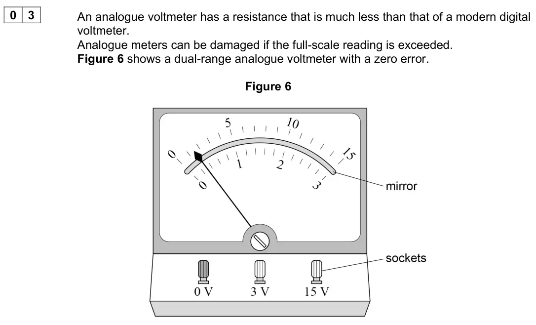
Q03.5
The whole paper ↗Q03.6
The whole paper ↗Q03.7
The whole paper ↗Q03.8
The whole paper ↗
All 74 questions on Capacitor charge and discharge, as a list
- June 2025, Paper 2, Q05.2 (2 marks): Determine T using Figure 4. [2 marks] T = s
- June 2025, Paper 2, Q05.3 (2 marks): Electronic engineers consider a capacitor to be fully discharged when t = 5T. Calculate = 5 = 0 t T t current when current hen w as a percentage. [2 marks] = 5
- June 2025, Paper 2, Q05.4 (3 marks): The capacitor is fully discharged and then the switch is moved from position B to position A as shown in Figure 3. Draw, on Figure 5, the variation of the micro
- June 2025, Paper 2, Q18 (1 mark): A capacitor is initially uncharged and is then charged using a constant current. This is achieved by reducing the resistance of a variable resistor R as the cha
- June 2025, Paper 3A, Q02.4 (5 marks): It can be shown that T = (R1 + 2R2)C ln2 Determine C and R1. [5 marks] C = F R1 = Ω
- June 2025, Paper 3A, Q02.5 (3 marks): The student has access to a range of fixed and variable resistors. The student wants to modify the circuit in Figure 3 so that T can be varied continuously from
- June 2024, Paper 2, Q02.1 (2 marks): The switch is closed at time t = 0 and the potential difference VC across C is recorded at different times t. Figure 2 shows the variation of VC with t. Figure
- June 2024, Paper 2, Q02.2 (2 marks): The potential difference VR across R is also recorded. Figure 3 shows the variation of VR with t between t = 20 s and t = 45 s. Figure 3 The capacitance of C is
- June 2024, Paper 2, Q02.3 (3 marks): The current I0 at time t = 0 is 3.6 × 10⁻⁵ A. Determine the time at which VC is 6.0 V. [3 marks] time = s
- June 2023, Paper 2, Q05.1 (3 marks): Show that the time taken for the capacitor to charge from 2.0 V to 4.0 V is approximately 0.7R1C. [3 marks]
- June 2023, Paper 2, Q05.2 (4 marks): Show that the capacitance of the capacitor is about 1 × 10⁻⁴ F. [4 marks]
- June 2023, Paper 2, Q05.3 (3 marks): When the pd reaches 4.0 V the switch is immediately set to discharge the capacitor. When the pd reaches 2.0 V the switch is immediately set to charge the capaci
- June 2022, Paper 2, Q18 (1 mark): A 30 μF capacitor is charged by connecting it to a battery of emf 4.0 V. The initial charge on the capacitor is Q0. The capacitor is then discharged through a 5
- June 2022, Paper 2, Q21 (1 mark): A fully charged capacitor of capacitance 2.0 mF discharges through a 15 kΩ resistor. What fraction of the stored energy remains after 1.0 minute? [1 mark] A 1 4
- November 2021, Paper 2, Q20 (1 mark): The capacitor in the circuit is initially uncharged. The switch is closed at time t = 0 Which pair of graphs shows how the potential difference V across the cap
- November 2021, Paper 3A, Q03.4 (1 mark): Show that the time constant for the discharge circuit is about 17 s. [1 mark]
- November 2021, Paper 3A, Q03.5 (4 marks): The student thinks that the time constant of the circuit in Figure 7 is directly proportional to the range of the meter. To test her theory, she repeats the exp
- November 2021, Paper 3A, Q03.6 (4 marks): Suggest two reasons why the student selected the values of V shown in Table 2. Explain each of your answers. [4 marks] 1 2
- November 2021, Paper 3A, Q03.7 (3 marks): Show, using Figure 8, that the resistance of the voltmeter is about 16 kΩ. [3 marks]
- November 2021, Paper 3A, Q03.8 (2 marks): Determine the current in the voltmeter at t = 10 s. [2 marks] current = A
- November 2020, Paper 2, Q04.5 (3 marks): Figure 9 shows the arrangement with the square-wave generator connected to an RC circuit. A capacitor C is placed in series with the resistor R. The oscilloscop
- November 2020, Paper 2, Q04.6 (2 marks): State and explain a change to one control setting on the oscilloscope that would reduce the uncertainty in the value of the time constant. [2 marks]
- November 2020, Paper 2, Q22 (1 mark): A 10 μF capacitor stores 4.5 mJ of energy. It then discharges through a 25 Ω resistor. What is the maximum current during the discharge of the capacitor? [1 mar
- June 2019, Paper 2, Q21 (1 mark): A 1.0 µF capacitor initially stores 15 µC of charge. It then discharges through a 25 Ω resistor. What is the maximum current during the discharge of the capacit
- June 2019, Paper 2, Q22 (1 mark): The initial potential difference across a capacitor is V0. The capacitor discharges through a circuit of time constant T. The base of natural logarithms is e. W
- June 2018, Paper 2, Q03.2 (1 mark): The charging of a 370 µF capacitor is investigated using the circuit shown in Figure 4. Both meters in the circuit are ideal. Figure 4 The power supply of emf 9
- June 2018, Paper 2, Q03.3 (2 marks): Identify, with the symbol X on Figure 5, the potential difference (pd) across the capacitor when the switch has been closed for 2.0 s Sketch the graph that show
- June 2018, Paper 2, Q03.4 (1 mark): Calculate the time taken for the charging current to fall to half its initial value. [1 mark] time = s
- June 2018, Paper 2, Q03.5 (3 marks): Calculate the time taken for the charge on the capacitor to reach 3.0 mC [3 marks] time = s
- June 2017, Paper 2, Q21 (1 mark): A capacitor of capacitance 120 µF is charged and then discharged through a 20 kΩ resistor. What fraction of the original charge remains on the capacitor 4.8 s a
- June 2017, Paper 3A, Q02.3 (2 marks): Figure 9 shows the signal generator connected in series with a resistor R and a capacitor C. Figure 9 The oscilloscope is connected across the capacitor. The Y-
- June 2017, Paper 3A, Q02.4 (3 marks): A student suggests that setting the time-base to 0.2 ms division–1 might reduce uncertainty in the determination of the time constant. State and explain any pos
- June 2017, Paper 3A, Q02.5 (2 marks): The student connects an identical resistor in parallel with R and uses the oscilloscope to display the waveform across C. Draw on Figure 11 the waveform you exp
- June 2017, Paper 3A, Q02.6 (2 marks): Figure 12a is a graph of voltage against time showing the output of the signal generator. Figure 12b shows the voltage across C during the same time interval. T
- June 2017, Paper 3A, Q02.7 (2 marks): State and explain what changes, if any, the student needs to make to the settings of the oscilloscope so the waveform across R is fully displayed. [2 marks]
- Specimen, Paper 2, Q17 (1 mark): A voltage sensor and a datalogger are used to record the discharge of a 10 mF capacitor in series with a 500 Ω resistor from an initial pd of 6.0 V. The datalog
- Specimen, Paper 3A, Q02.1 (1 mark): This question is about capacitor charging and discharging. A student designs an experiment to charge a capacitor using a constant current. Figure 3 shows the ci
- Specimen, Paper 3A, Q02.3 (2 marks): This question is about capacitor charging and discharging. A student designs an experiment to charge a capacitor using a constant current. Figure 3 shows the ci
- Specimen, Paper 3A, Q02.8 (4 marks): This question is about capacitor charging and discharging. A student designs an experiment to charge a capacitor using a constant current. Figure 3 shows the ci
- June 2016, PHYA4 Section A (old spec), Q20 (1 mark): The capacitor in the circuit is initially uncharged. The switch S is closed at time t = 0. Which pair of graphs, A to D, correctly shows how the pd across the c
- June 2016, PHYA4 Section B (old spec), Q1(b)(i) (3 marks): Calculate the time constant of the capacitor–resistor circuit. [3 marks] time constant = ____________________________ s
- June 2016, PHYA4 Section B (old spec), Q1(b)(ii) (2 marks): Determine the resistance of R. [2 marks] resistance = ___________________________ Ω
- June 2016, PHYA4 Section B (old spec), Q1(b)(iii) (1 mark): At which point during the discharging process is the capacitor losing charge at the smallest rate? Tick () the correct answer. [1 mark] if correct when the ch
- June 2015, PHYA4 Section B (old spec), Q3(a)(i) (1 mark): Explain how the initial charge on the capacitor could be determined from a graph of current against time. [1 mark]
- June 2015, PHYA4 Section B (old spec), Q3(a)(ii) (3 marks): The same capacitor is charged to the same initial potential difference (pd) and then discharged through a 300 kΩ resistor. Sketch a second graph on the same axe
- June 2014, PHYA4 Section A (old spec), Q20 (1 mark): Switch S in the circuit is held in position 1, so that the capacitor C becomes fully charged to a pd V and stores energy E. The switch is then moved quickly to
- June 2014, PHYA4 Section B (old spec), Q4(b) (6 marks): The circuit in Figure 6 contains a cell, an uncharged capacitor, a fixed resistor and a two-way switch. Figure 6 The switch is moved to position 1 until the cap
- June 2013, PHYA4 Section A (old spec), Q21 (1 mark): In the circuit shown the capacitor C charges when switch S is closed. Which line, A to D, in the table gives a correct pair of graphs showing how the charge on
- June 2013, PHYA4 Section A (old spec), Q22 (1 mark): The voltage across a capacitor falls from 10V to 5V in 48ms as it discharges through a resistor. What is the time constant of the circuit? A 24ms B 33ms C 69ms
- January 2013, PHYA4 Section B (old spec), Q3(a) (3 marks): Determine the time constant, in ms, of the discharge circuit. time constant ms (3 marks)
- January 2013, PHYA4 Section B (old spec), Q3(b) (2 marks): Explain why the rate of discharge will be greater if the fixed resistor has a smaller resistance. (2 marks)
- June 2012, PHYA4 Section A (old spec), Q18 (1 mark): A voltage sensor and a datalogger are used to record the discharge of a 10mF capacitor in series with a 500Ω resistor from an initial pd of 6.0V. The datalogger
- June 2012, PHYA4 Section A (old spec), Q19 (1 mark): When a 220μF capacitor is discharged through a resistor R, the capacitor pd decreases from 6.0V to 1.5V in 92s. What is the resistance of R? A 210kΩ B 300kΩ C 4
- January 2012, PHYA4 Section B (old spec), Q2(b)(ii) (2 marks): The time constant for this circuit is the time taken for the charge stored to increase from 0 to 63% of its final value. Use the graph to find the time constant
- January 2012, PHYA4 Section B (old spec), Q2(b)(iii) (1 mark): Hence calculate the resistance of the resistor. answer = Ω (1 mark)
- January 2012, PHYA4 Section B (old spec), Q2(b)(iv) (1 mark): What physical quantity is represented by the gradient of the graph? (1 mark)
- January 2012, PHYA4 Section B (old spec), Q2(c)(i) (1 mark): Calculate the maximum value of the current, in mA, in this circuit during the charging process. answer = mA (1 mark)
- January 2012, PHYA4 Section B (old spec), Q2(c)(ii) (2 marks): Sketch a graph on the outline axes to show how the current varies with time as the capacitor is charged. Mark the maximum value of the current on your graph. (2
- June 2011, PHYA4 Section A (old spec), Q19 (1 mark): A capacitor of capacitance C discharges through a resistor of resistance R. Which one of the following statements is not true? A The time constant will decrease
- June 2011, PHYA4 Section A (old spec), Q20 (1 mark): The graph shows how the charge on a capacitor varies with time as it is discharged through a resistor. What is the time constant for the circuit? A 3.0s B 4.0s
- January 2011, PHYA4 Section B (old spec), Q3(a) (6 marks): Describe the procedure the student should follow, including the measurements he should make, when using this arrangement. Explain how he should use the measurem
- January 2011, PHYA4 Section B (old spec), Q3(b)(i) (3 marks): From the student’s result, calculate the time taken for the cylinder to reach the second plunger. answer = s (3 marks)
- June 2010, PHYA4 Section A (old spec), Q17 (1 mark): When switch S in the circuit is closed, the capacitor C is charged by the battery to a pd V0. The switch is then opened until the capacitor pd decreases to 0.5
- June 2010, PHYA4 Section A (old spec), Q18 (1 mark): When a capacitor discharges through a resistor it loses 50% of its charge in 10s. What is the time constant of the capacitor-resistor circuit? A 0.5 s B 5 s C 1
- January 2010, PHYA4 Section B (old spec), Q2(a)(i) (1 mark): Calculate the initial discharge current. answer = A (1 mark)
- January 2010, PHYA4 Section B (old spec), Q2(a)(ii) (4 marks): Use the graph to determine the time constant of the circuit, giving an appropriate unit. answer = (4 marks)
- January 2010, PHYA4 Section B (old spec), Q2(a)(iii) (1 mark): Hence calculate the capacitance of the capacitor. answer = µF (1 mark)
- January 2010, PHYA4 Section B (old spec), Q2(a)(iv) (3 marks): Show that the capacitor lost 90% of the energy it stored originally after about 25s. (3 marks)
- January 2010, PHYA4 Section B (old spec), Q2(b)(ii) (1 mark): State and explain the effect of this higher initial pd on the time taken for this capacitor to lose 90% of its original energy. (1 mark)
- June 2008, PA04A (2008 spec), Q6 (2 marks): 6 An uncharged capacitor of Þ xed capacitance is connected in series with a switch and battery. The switch is closed at time t = 0. Which graph, A to D, shows h
- June 2008, PA04A (2008 spec), Q7 (2 marks): 7 The voltage across a capacitor falls from 10 V to 5 V in 48 ms as it discharges through a resistor. What is the time constant of the circuit? A 24 ms B 33 ms
- June 2008, PHA9W (2008 spec), Q2(c) (3 marks): 2 (c) A smoothing capacitor is to be added to the circuit. The use of a capacitor of capacitance 22 µF is suggested for this circuit. Explain, using appropriate
- January 2008, PA04B (2008 spec), Q2(a) (3 marks): 2 (a) An experiment is to be carried out to determine the capacitance of a capacitor by measuring the potential difference V across it at various times t as it
- January 2008, PA04B (2008 spec), Q2(b) (5 marks): (b) A similar experiment, in which the resistor had a resistance of 91 kΩ, gave the graph of ln V against t shown on the opposite page. Use this graph to calcul
Questions, mark schemes and examiner’s reports are © AQA, from their published past papers. Plumi isn’t affiliated with any exam board. Want whole papers? AQA A-Level Physics past papers.
The Plumi iPad app also offers exam-style questions with AI feedback on your handwritten working.