 plumi
Current–voltage characteristics: AQA A‑Level Physics questions
AQA A-Level Physics past-paper questions on 3.5.1.2 Current–voltage characteristics, 2008–2025, with mark schemes and examiner’s reports where available.
Paper
All papers
Exam
All years
Calculations
Q06.1
The whole paper ↗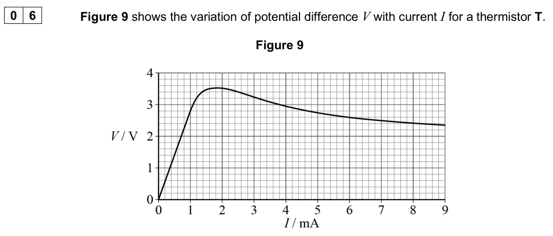
Q05.1
The whole paper ↗
Q02.1
The whole paper ↗
Q06.3
The whole paper ↗Q08.2
The whole paper ↗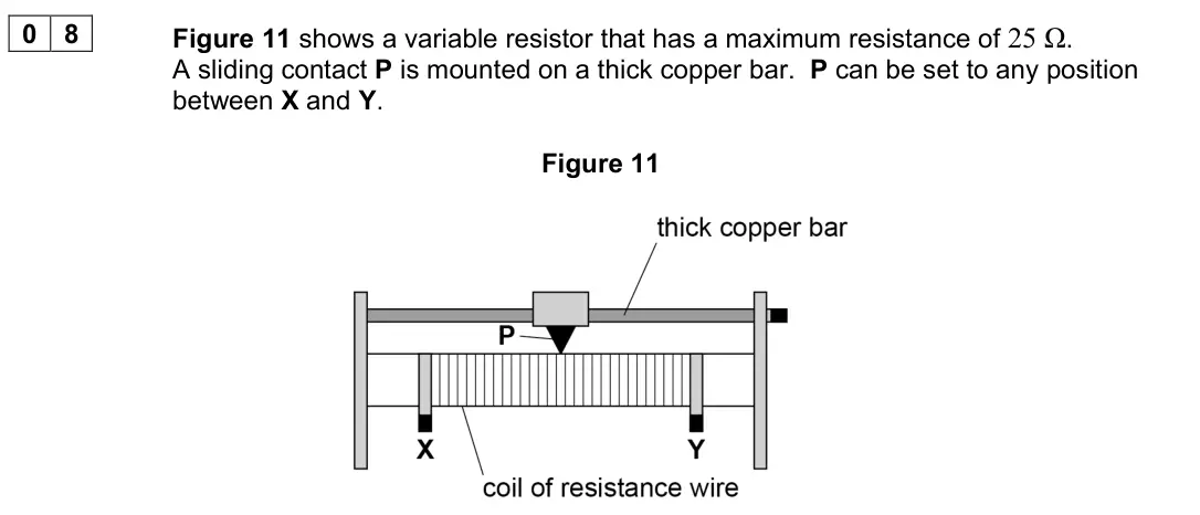
Q08.3
The whole paper ↗Q02.3
The whole paper ↗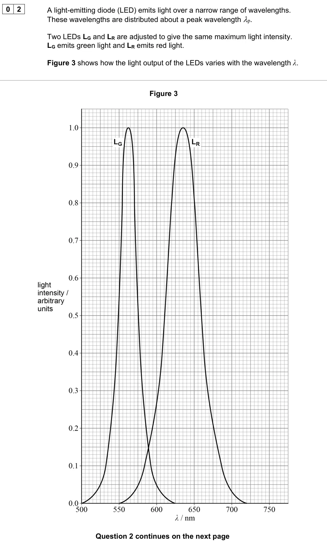
Q02.5
The whole paper ↗Q02.3
The whole paper ↗
Q02.1
The whole paper ↗
Q02.2
The whole paper ↗Q02.3
The whole paper ↗- Your answer
- Your answer
All 52 questions on Current–voltage characteristics, as a list
- June 2025, Paper 1, Q16 (1 mark): The graph shows the I–V characteristic for a semiconductor diode. Which is true for this graph? [1 mark] A The resistance of the diode decreases as V increases
- June 2025, AS Paper 1, Q06.1 (6 marks): Discuss, for the range 0 to 9 mA, the characteristic of T shown by Figure 9. In your answer you should: • describe how to produce a characteristic experimentall
- June 2025, AS Paper 2, Q18 (1 mark): The characteristics of four electrical components A, B, C and D are shown in the table. The table shows values of potential difference V across each component a
- June 2024, AS Paper 1, Q05.1 (1 mark): The current in L1 is increased from 0 to 0.50 A. The potential difference V across L1 is 0.375 V when I is 0.50 A. Draw, on Figure 14, a V–I graph for L1 in the
- June 2023, Paper 3A, Q02.1 (2 marks): Determine, in V s−1, the rate of increase of V. [2 marks] rate of increase of V = V s−1
- June 2023, AS Paper 1, Q06.3 (3 marks): Determine the power output of one LED when the torch is on. [3 marks] power output = W
- June 2023, AS Paper 2, Q31 (1 mark): The current–voltage characteristic between 0 and 6.0 V is required for a filament lamp. The lamp is connected in a circuit with a battery of emf 6.0 V and negli
- June 2022, AS Paper 1, Q08.2 (2 marks): Figure 13 shows the variation of current with voltage for the lamp between 2 V and 12 V. Figure 13 Calculate the resistance of the lamp when the voltage across
- June 2022, AS Paper 1, Q08.3 (3 marks): Explain, in terms of electron movement, why the resistance of the filament lamp changes as the voltage changes as shown in Figure 13. [3 marks]
- November 2021, Paper 3A, Q02.3 (2 marks): Figure 4 shows part of the current−voltage characteristics for LR and LG. Figure 4 When the linear part of the characteristic is extrapolated, the point at whic
- November 2021, Paper 3A, Q02.5 (2 marks): Figure 5 shows a circuit with LR connected to a resistor of resistance R. Figure 5 The power supply has emf 6.10 V and negligible internal resistance. The curre
- November 2021, AS Paper 2, Q31 (1 mark): The graph shows the current–voltage (I–V) characteristics for two components. The two components are connected in parallel with a 12 V battery that has negligib
- November 2020, AS Paper 2, Q28 (1 mark): The table shows corresponding values of potential difference V and current I for four electrical components A, B, C and D. A B C D V / V I / A I / A I / A I / A
- June 2019, AS Paper 1, Q02.3 (4 marks): A light emitting diode (LED) is used to indicate that the switch in the glove is closed, as shown in Figure 1. Resistor R limits the current in the LED. Figure
- June 2019, AS Paper 2, Q02.1 (1 mark): Draw a best-fit line for the data on Figure 3. [1 mark]
- June 2019, AS Paper 2, Q02.2 (1 mark): Identify the data point with the greatest value of current and voltage at which R obeys Ohm’s law. Draw a circle around this data point on Figure 3. [1 mark]
- June 2019, AS Paper 2, Q02.3 (2 marks): When R obeys Ohm’s law it has a resistance of 22.2 Ω. Determine the percentage increase in the resistance of R from its 22.2 Ω value to its value when the curre
- June 2019, AS Paper 2, Q29 (1 mark): Which is the current–voltage characteristic graph for a filament lamp up to its working voltage? [1 mark] A B C D A B C D
- June 2018, Paper 1, Q28 (1 mark): A voltmeter is used to measure potential difference for a component X. Which row gives the position and ideal resistance for the voltmeter? [1 mark] Position Id
- June 2018, AS Paper 2, Q30 (1 mark): The graph shows how the potential difference V across an electrical component varies with current I in the component. A tangent has been drawn on the curve at p
- June 2017, AS Paper 1, Q02.1 (4 marks): Explain, in terms of electron motion, why the I–V characteristic for the filament lamp is a curve. [4 marks]
- June 2017, AS Paper 1, Q02.2 (1 mark): Determine the resistance of the resistor. [1 mark] resistance = Ω
- June 2017, AS Paper 1, Q02.3 (3 marks): The resistor and the filament lamp are connected in series with a supply of variable emf and negligible internal resistance. Determine the emf that produces a c
- June 2017, AS Paper 1, Q02.4 (3 marks): The resistor and filament lamp are now connected in parallel. Determine the resistance of the parallel combination when the emf of the supply is adjusted to be
- June 2016, AS Paper 2, Q29 (1 mark): A resistor and diode are connected in series with a variable power supply as shown in the diagram. Which best shows the characteristic for the combination of th
- June 2016, PHYA1 (old spec), Q5(a)(i) (2 marks): Draw a labelled circuit diagram of the apparatus that the student could use to obtain the part of the characteristic from O to A. [2 marks]
- June 2016, PHYA1 (old spec), Q5(a)(ii) (6 marks): Describe how the student could use the circuit in part (a)(i) to obtain sufficient measurements to draw the part of the characteristic from O to A. Your account
- June 2016, PHYA1 (old spec), Q5(a)(iii) (1 mark): Suggest how the circuit you drew in part (a)(i) could be modified to obtain the characteristic from O to B. [1 mark] ___________________________________________
- June 2016, PHYA1 (old spec), Q5(b)(i) (2 marks): Describe how the student could use the characteristic to determine how the resistance varies as the potential difference (pd) between O and A increases. [2 mark
- June 2016, PHYA1 (old spec), Q5(b)(ii) (1 mark): State how you would expect the resistance of the diode to vary as the pd increases. [1 mark] ___________________________________________________________________
- June 2015, PHYA1 (old spec), Q5(a) (2 marks): Sketch, on Figure 1, the current–voltage (IV) characteristic for a filament lamp for currents up to its working power. [2 marks] Figure 1 I V
- June 2015, PHYA1 (old spec), Q5(b)(i) (1 mark): State what happens to the resistance of the filament lamp as the current increases. [1 mark]
- June 2015, PHYA1 (old spec), Q5(b)(ii) (1 mark): State and explain whether a filament lamp is an ohmic or non-ohmic conductor up to its working power. [1 mark]
- January 2013, PHYA1 (old spec), Q5(a) (1 mark): State what is meant by an ohmic conductor. (1 mark)
- January 2013, PHYA1 (old spec), Q5(b)(i) (2 marks): Draw a suitable circuit diagram for such an experiment. (2 marks)
- January 2013, PHYA1 (old spec), Q5(b)(ii) (6 marks): For the circuit diagram you have drawn, describe a suitable experiment. Your account should include details of: l what measurements you would take l how you wou
- January 2011, PHYA1 (old spec), Q6(a) (1 mark): Use the graph to determine the maximum current through the lamp. answer = A (1 mark)
- January 2011, PHYA1 (old spec), Q6(c) (2 marks): Explain why the current through the lamp decreases between 0.05s and 0.50s.
- January 2011, PHYA1 (old spec), Q6(e) (2 marks): State and explain why a filament lamp is most likely to fail as it is switched on. (2 marks)
- June 2010, PHYA1 (old spec), Q6(a) (1 mark): A semiconducting diode is an example of a non-ohmic component. State what is meant by a non-ohmic component. (1 mark)
- June 2010, PHYA1 (old spec), Q6(b)(i) (2 marks): Sketch on the axes below the current-voltage characteristic for a filament lamp. (2 marks) current pd
- June 2010, PHYA1 (old spec), Q6(b)(ii) (1 mark): State, with reference to the current-voltage characteristic you have drawn, how the resistance of the lamp changes as the pd across its terminals changes. (1 ma
- June 2010, PHYA1 (old spec), Q6(c)(ii) (3 marks): A student predicts that if the pd across the bulb is reduced to 6.0V the power rating of the bulb would be 9.0W. State and explain how in practice the power rat
- June 2009, PHYA1 (old spec), Q5(a)(i) (3 marks): Draw a suitable diagram of the circuit that would enable the student to collect this data. (3 marks)
- June 2009, PHYA1 (old spec), Q5(a)(ii) (6 marks): Describe the procedure the student would follow in order to obtain an I-V curve for the semiconductor diode. The quality of your written communication will be a
- June 2009, PHYA1 (old spec), Q5(b)(ii) (3 marks): Calculate the current in the 4.0 Ω resistor if the p.d. across the diode, when in forward bias, is 0.65 V expressing your answer to an appropriate number of sig
- January 2009, PHA3W (2008 spec), Q1(a) (8 marks): 1 (a) (i) Draw a suitable circuit diagram for this investigation. 1 (a) (ii) Use the axes below to sketch a graph showing how the current through the lamp varie
- June 2008, PHA3W (2008 spec), Q2(a) (7 marks): 2 (a) A student is required to carry out an experiment and to draw a suitable graph in order to obtain a value for the resistance of a resistor. You may be awar
- June 2008, PHA9W (2008 spec), Q2(a) (1 mark): 2 (a) Explain why the peak voltage across the load resistor is about 2.3 V. (1 mark)
- June 2008, PHA9W (2008 spec), Q2(b) (2 marks): 2 (b) The oscilloscope was set to a voltage sensitivity of 1 V cm –1 and a time base of 5 ms cm –1. Draw on the grid the trace that would be seen on the oscillo
- January 2008, PHA3W (2008 spec), Q3(a) (5 marks): (a) (i) Draw the circuit diagram of an experimental arrangement which could be used to collect the data necessary to produce this graph. Your circuit should inc
- January 2008, PHA3W (2008 spec), Q3(b) (4 marks): (b) Explain the shape of the complete I – V characteristic. You may be awarded additional marks to those shown in brackets for the in your answer. (4 marks)
Questions, mark schemes and examiner’s reports are © AQA, from their published past papers. Plumi isn’t affiliated with any exam board. Want whole papers? AQA A-Level Physics past papers.
The Plumi iPad app also offers exam-style questions with AI feedback on your handwritten working.