 plumi
Potential dividers and sensors: OCR A‑Level Physics B questions
OCR A-Level Physics B past-paper questions on 3.1.2.4 Potential dividers and sensors, 2016–2025, with mark schemes and examiner’s reports where available.
Paper
All papers
Exam
All years
Calculations
Q4(a)(ii)
The whole paper ↗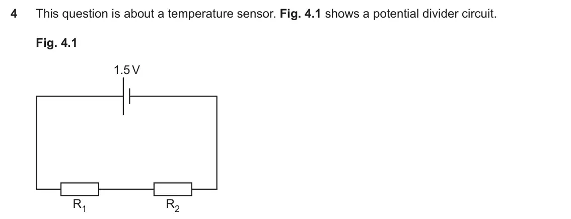
Q4(b)(ii)
The whole paper ↗Q6(a)
The whole paper ↗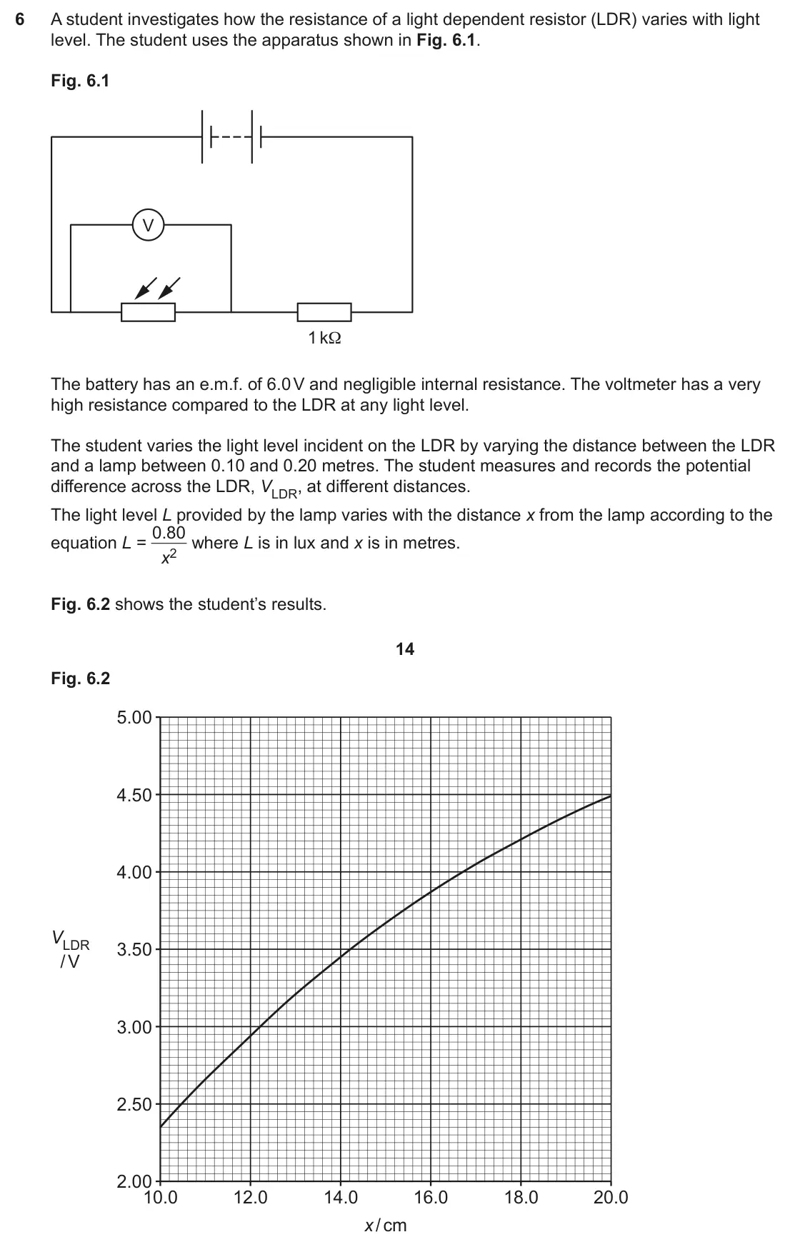
Q6(b)
The whole paper ↗Q6(c)
The whole paper ↗- Your answer
Q21(c)
The whole paper ↗Q37(a)(i)
The whole paper ↗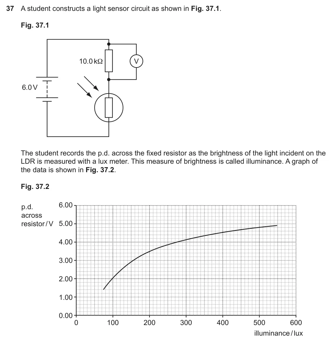
Q37(a)(ii)
The whole paper ↗- Your answer
- Your answer
- Your answer
Q8(a)(i)
The whole paper ↗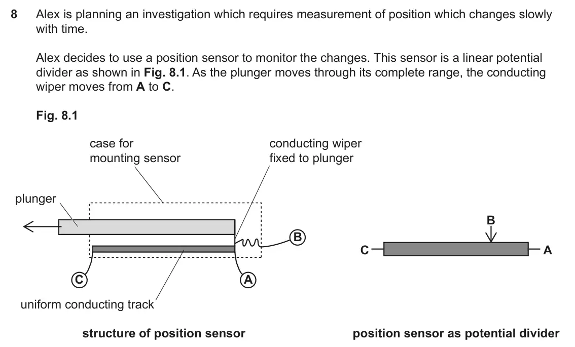
Q8(a)(ii)
The whole paper ↗Q8(b)(i)
The whole paper ↗Q8(d)
The whole paper ↗Q3(a)(i)
The whole paper ↗
Q3(a)(ii)
The whole paper ↗Q3(a)(iii)
The whole paper ↗
All 59 questions on Potential dividers and sensors, as a list
- June 2025, Paper 2, Q4(a)(ii) (2 marks): R1 has a resistance of 30 Ω. Calculate the resistance of R2. resistance = Ω [2]
- June 2025, Paper 2, Q4(b)(i) (3 marks): Describe an experimental method that could be used to obtain such a calibration curve. Give one possible source of experimental uncertainty and suggest how it c
- June 2025, Paper 2, Q4(b)(ii) (6 marks): This question is about a temperature sensor. Fig. 4.1 shows a potential divider circuit. Fig. 4.1 1.5 V R1 R2 (ii)* The ideal temperature for a baby bath is 37
- June 2025, AS Paper 2, Q6(a) (6 marks): A student investigates how the resistance of a light dependent resistor (LDR) varies with light level. The student uses the apparatus shown in Fig. 6.1. Fig. 6.
- June 2025, AS Paper 2, Q6(b) (3 marks): Explain why the voltmeter used in the experiment should have a very high resistance. [3]
- June 2025, AS Paper 2, Q6(c) (3 marks): Fig. 6.4 shows how the circuit in Fig. 6.1 can be adapted and used as part of a burglar alarm. Fig. 6.4 Alarm The alarm switches on when the burglar’s torch shi
- June 2024, Paper 1, Q27 (1 mark): The diagram shows seven identical resistors connected in a circuit with a 6 V battery. 6 V P Q R S T Which pair of points has a potential difference of 0.5 V be
- June 2024, AS Paper 1, Q21(c) (2 marks): Determine the resistance of component R2. Resistance = Ω [2]
- June 2023, Paper 1, Q37(a)(i) (2 marks): Use data from the circuit diagram and the graph to show that the resistance of the LDR is about 7 kΩ when the illuminance of the light is 200 lux. [2]
- June 2023, Paper 1, Q37(a)(ii) (2 marks): Use Fig. 37.2 to determine the sensitivity of the sensor at an illuminance of 200 lux. sensitivity = V / lux [2]
- June 2023, AS Paper 1, Q10 (1 mark): A scale is marked on a thermometer by first placing it in ice at 0 °C and then steam at 100 °C. This process is an example of: A accuracy B calibration C precis
- June 2023, AS Paper 1, Q13 (1 mark): The graph shows the output p.d. of a temperature sensor at different temperatures, θ. 5 p.d. / V 4 3 2 1 0 0 10 20 30 40 50 60 70 80 90 100 θ/ °C Estimate the s
- June 2023, AS Paper 1, Q16 (1 mark): Estimate the reading on the ammeter in this circuit. 6 V 100 Ω 47 Ω A 100 Ω A 20 mA B 30 mA C 40 mA D 60 mA Your answer [1]
- June 2023, AS Paper 2, Q8(a)(i) (2 marks): Draw and label fully the circuit diagram described above. [2]
- June 2023, AS Paper 2, Q8(a)(ii) (2 marks): The p.d. VAB is to be used to calculate the resistance of the active length AB of the sensor. Explain why the voltmeter should have a resistance much higher tha
- June 2023, AS Paper 2, Q8(b)(i) (2 marks): Alex did not take readings of VAB at uniform intervals of d. By referring to the data in the table, explain why this was an appropriate decision. [2]
- June 2023, AS Paper 2, Q8(d) (6 marks): Alex is planning an investigation which requires measurement of position which changes slowly with time. Alex decides to use a position sensor to monitor the ch
- June 2022, Paper 2, Q3(a)(i) (2 marks): The student had a choice of three resistors for the strain potential divider; 100 Ω, 470 Ω and 2000 Ω. Suggest and explain why they chose the 470 Ω resistor. [2
- June 2022, Paper 2, Q3(a)(ii) (2 marks): Show that the p.d. across the resistor when the gauge is not under strain is about 3.6 V [2]
- June 2022, Paper 2, Q3(a)(iii) (2 marks): The p.d. across the resistor drops to 3.57 V when the gauge experiences a tensile force. Calculate the resistance of the gauge in this case. resistance = Ω [2]
- June 2022, Paper 2, Q3(b) (4 marks): Two gauges are fixed on a beam, clamped at one end, as indicated in Fig. 3.3a. gauge 1 clamp beam gauge 2 Fig. 3.3a (not to scale) Fig. 3.3b (not to scale) When
- June 2022, AS Paper 1, Q21(b) (2 marks): At the start, the resistance of the thermistor is 36 kΩ. Calculate the reading on the meter. reading = mA [2]
- June 2022, AS Paper 1, Q21(c) (2 marks): For the thermistor used in this circuit, the resistance increases as the temperature decreases. Explain what happens to the reading on the ammeter if the temper
- June 2022, AS Paper 2, Q3(a) (2 marks): Calculate the p.d. recorded by the voltmeter. Assume that the internal resistance of the battery is negligible. p.d. = V [2]
- November 2021, Paper 1, Q27 (1 mark): The diagram shows a combination of three resistors connected to a 6.0 V power supply of negligible internal resistance. 6.0 V 300 Ω 100 Ω R A voltmeter connecte
- November 2021, AS Paper 1, Q8 (1 mark): 20 Ω 40 Ω V V V1 = 5 V V2 = ? In this circuit the reading on the voltmeter V2 is A 2.5 V B 5 V C 10 V D 40 V Your answer [1]
- November 2020, Paper 1, Q23 (1 mark): Which answer gives the correct output voltage range? Voltage range Vout / V A 0 12 B 2 10 C 3 9 D 4 8 Your answer [1]
- November 2020, Paper 1, Q24 (1 mark): The potential divider is set to its mid-point with Vout = 6.0 V. A 200 Ω resistance is connected across the output. Which statement about Vout is correct? A It
- November 2020, Paper 3, Q2(b)(i) (2 marks): Explain why the output reading on the voltmeter will increase as light intensity increases. [2] 8 Fig. 2.3 shows a graph of intensity against 1 x2. 100 90 80 70
- November 2020, Paper 3, Q2(b)(ii) (3 marks): Use the graph in Fig. 2.3 to complete the third column and then plot the points and complete the calibration curve in Fig. 2.4. [3] 9 100 90 80 70 60 light 50 i
- November 2020, Paper 3, Q2(c) (6 marks): This question is about calibrating a light meter to measure the intensity of light emitted by a torch. (c)* Use the calibration plots in this question to find t
- November 2020, AS Paper 1, Q19 (1 mark): The graph shows how the resistance of four different components changes with temperature. Which component would be best to use as a temperature sensor for a dom
- November 2020, AS Paper 1, Q24(a) (1 mark): State the name of the component marked X. [1] The variable resistor is set to 18 kΩ. When the p.d. across the digital switch is 6.0 V it turns on the room light
- November 2020, AS Paper 1, Q24(b) (2 marks): Calculate the resistance of component X when this happens. resistance = Ω [2]
- November 2020, AS Paper 1, Q24(c) (2 marks): Describe the steps the manufacturer must take to calibrate the sensor so that the switch turns on the light when the room is just dark enough. [2]
- November 2020, AS Paper 2, Q4(a) (2 marks): The temperature of the thermistor is increased. Without doing any calculations, describe and explain what will be observed on the voltmeter V during the tempera
- November 2020, AS Paper 2, Q4(b)(i) (3 marks): Calculate the resistance of the thermistor at this temperature. resistance = Ω [3]
- November 2020, AS Paper 2, Q4(b)(ii) (1 mark): Use the data in the table to make an estimate of the temperature. temperature = °C [1]
- June 2019, Paper 1, Q9 (1 mark): The circuit shows a potential divider with resistors of R and 4R. V R 4R power dissipated in resistor R What is the ratio power dissipated in resistor 4R? 1 A 1
- June 2019, Paper 1, Q23 (1 mark): An LDR is used in a potential divider circuit. 3 V R LDR R V The graph shows the LDR resistance against light intensity. LDR resistance R LDR / kΩ 40 30 20 10 0
- June 2019, Paper 2, Q2(a) (1 mark): Show that the potential difference across the 4.7 kΩ resistor is 4.2 V to 2 significant figures. [1]
- June 2019, Paper 2, Q2(b) (3 marks): An analogue voltmeter connected across the 4.7 kΩ resistor reads 3.2 V. Show that the resistance of the voltmeter is about 5 kΩ. [3]
- June 2019, AS Paper 1, Q14 (1 mark): In the circuit shown, the p.d. across the 2.0 Ω resistor is 6.0 V 1.0 Ω 2.0 Ω A 2.0 V B 3.0 V C 4.0 V D 6.0 V Your answer [1]
- June 2019, AS Paper 1, Q26(b) (2 marks): Calculate the voltmeter reading you expect the student to see. Expected reading = V [2] 23 The student records the readings on the voltmeter and ammeter for a r
- June 2018, Paper 1, Q16 (1 mark): A thermistor is used in a potential divider circuit. thermistor resistance RT / kΩ 40 3 V 30 20 RT R 10 0 V 0 10 20 30 40 50 60 70 Circuit temperature / °C When
- June 2018, Paper 2, Q1(b)(i) (4 marks): Describe and explain how the p.d. across the LDR changes as the second filter is rotated through 360° from its original orientation. You do not need to give val
- June 2018, Paper 2, Q1(b)(ii) (2 marks): The highest p.d. recorded by the voltmeter is 3.00 ± 0.01 V. Calculate the maximum value of the resistance of the LDR at this point. Assume that there is no unc
- June 2018, Paper 3, Q1(a)(i) (2 marks): Show that the resistance R of the filament bulb Y in this circuit is approximately 2 Ω. [2] The bulb is broken and the diameter of the filament wire is measured
- June 2018, AS Paper 1, Q29(a) (4 marks): State suitable apparatus (other than indicated in Fig. 29.1) and describe how to use it to obtain the calibration graph shown in Fig. 29.2. You may wish to incl
- June 2018, AS Paper 1, Q29(b) (2 marks): The p.d. across the terminals of the power supply is 6.0 V and the resistance of the fixed resistor in the potential divider is 470 Ω. Calculate the resistance
- June 2018, AS Paper 1, Q29(c)(i) (2 marks): The sensitivity of the sensor is the ratio change in temperature. Describe how the sensitivity of the sensor varies between 0 °C and 100 °C. Explain your reason
- June 2017, Paper 1, Q6 (1 mark): A battery of e.m.f. 12 V and negligible internal resistance is connected across X Y. What is the magnitude of the p.d. between L and M? A 2 V B 4 V C 6 V D 8 V
- June 2017, Paper 2, Q2(a) (2 marks): Show that the p.d. across the 4.7 kΩ resistor in the circuit in Fig. 2.1 is about 4 V, assuming that the cell has zero internal resistance. [2]
- June 2017, Paper 3, Q1(a) (2 marks): The resistance of the thermistor can be measured with a multimeter on the resistance range. Suggest how you might vary and measure the temperature of the thermi
- June 2017, Paper 3, Q1(b) (1 mark): Suggest why the voltmeter is connected across the fixed resistor Q rather than the thermistor in this temperature sensing circuit. [1]
- June 2017, Paper 3, Q1(c)(ii) (2 marks): Explain how you could calibrate the analogue voltmeter scale to read temperature directly. [2]
- June 2017, Paper 3, Q1(d) (6 marks): This question is about using a thermistor in a temperature sensing circuit. The graph, Fig. 1.1, shows how the resistance R of a thermistor varies with temperat
- June 2017, AS Paper 1, Q6 (1 mark): In the circuit below, the thermistor conducts better at higher temperatures. V Which set of conditions produces the highest reading on the voltmeter? A high lig
- June 2016, AS Paper 2, Q3(b) (3 marks): The table below shows typical values of light intensity in different situations. The SI unit of intensity is the lux. night sky with Situation home lighting off
Questions, mark schemes and examiner’s reports are © OCR, from their published past papers. Plumi isn’t affiliated with any exam board. Want whole papers? OCR A-Level Physics B past papers.
The Plumi iPad app also offers exam-style questions with AI feedback on your handwritten working.