 plumi
The ideal operational amplifier: AQA A‑Level Physics questions
AQA A-Level Physics past-paper questions on 3.13.3.2 The ideal operational amplifier, 2008–2025, with mark schemes and examiner’s reports where available.
Paper
All papers
Exam
All years
Calculations
Q02.1
The whole paper ↗
Q02.2
The whole paper ↗Q02.3
The whole paper ↗Q03.4
The whole paper ↗Q02.4
The whole paper ↗
Q04.3
The whole paper ↗Q01.1
The whole paper ↗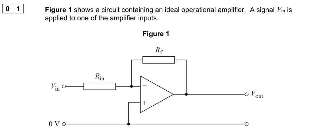
Q01.2
The whole paper ↗Q01.3
The whole paper ↗Q01.4
The whole paper ↗Q03.4
The whole paper ↗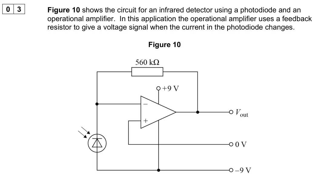
Q04.1
The whole paper ↗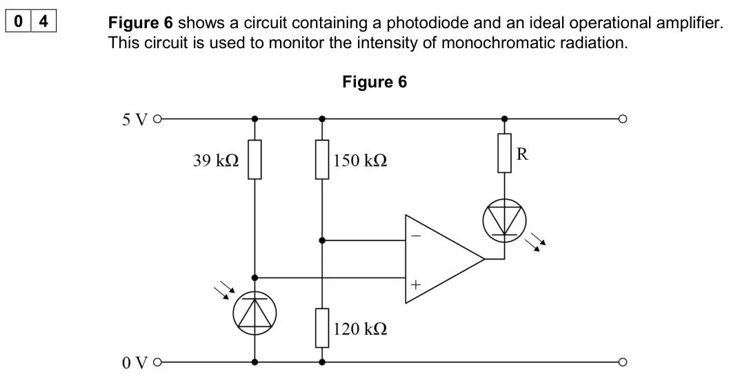
Q04.2
The whole paper ↗Q04.3
The whole paper ↗Q02.1
The whole paper ↗
Q02.2
The whole paper ↗Q02.3
The whole paper ↗Q02.1
The whole paper ↗Q04.2
The whole paper ↗
Q04.5
The whole paper ↗
All 26 questions on The ideal operational amplifier, as a list
- June 2025, Paper 3 Electronics, Q02.1 (1 mark): Explain the combined role of the 33 kΩ resistor and C in this circuit. [1 mark]
- June 2025, Paper 3 Electronics, Q02.2 (1 mark): State the function of the potential divider formed by the three 100 kΩ resistors. [1 mark]
- June 2025, Paper 3 Electronics, Q02.3 (3 marks): Deduce the voltage V+ at the non-inverting input of the operational amplifier when: • the output voltage Vout is 0.0 V • the output voltage Vout is 9.0 V. [3 ma
- June 2025, Paper 3 Electronics, Q03.4 (3 marks): Stage 3 uses an operational amplifier as a comparator to determine whether the irradiance detected by the photodiode in stage 1 exceeds a critical value. Figure
- June 2024, Paper 3 Electronics, Q02.4 (2 marks): Draw, on Figure 7, the output signal Vout from the circuit. Assume that Vout is initially at 5 V. [2 marks]
- June 2024, Paper 3 Electronics, Q04.3 (3 marks): The particle detector produces an analogue signal that is the input voltage Vin to an amplifier circuit. Vin is amplified by a factor of +10 Draw, on Figure 12,
- June 2022, Paper 3 Electronics, Q01.1 (1 mark): Draw an X on the circuit in Figure 1 to indicate a virtual earth point. [1 mark]
- June 2022, Paper 3 Electronics, Q01.2 (2 marks): Show that the closed loop voltage gain for the amplifier in Figure 1 is given by: State any assumptions made in your answer. [2 marks] assumptions Rf Rin out Vi
- June 2022, Paper 3 Electronics, Q01.3 (2 marks): Figure 2A shows the input signal Vin that is applied to the circuit in Figure 1. Figure 2A Figure 2B The circuit in Figure 1 has a closed loop gain of −20 and h
- June 2022, Paper 3 Electronics, Q01.4 (3 marks): A student converts the circuit in Figure 1 into one that will add two input signals V1 and V2 . The new circuit produces an output voltage Vout so that: Vout =
- November 2021, Paper 3 Electronics, Q03.4 (3 marks): The output from the detector circuit in Figure 10 needs to be amplified by a factor of +4 Complete Figure 12 to show the amplifier circuit required. In your com
- November 2020, Paper 3 Electronics, Q04.1 (1 mark): What is the configuration of the operational amplifier circuit shown in Figure 6? Tick () one box. [1 mark] comparator differential amplifier inverting amplifi
- November 2020, Paper 3 Electronics, Q04.2 (3 marks): Figure 7 shows the variation of photocurrent with intensity for the monochromatic radiation incident on the photodiode. Figure 7 Radiation of intensity 3.0 W m−
- November 2020, Paper 3 Electronics, Q04.3 (2 marks): The intensity of radiation incident on the photodiode remains at 3.0 W m−2. Deduce whether the light-emitting diode (LED) in Figure 6 is on or off. [2 marks]
- June 2019, Paper 3 Electronics, Q02.1 (1 mark): What is the operational amplifier configuration shown in Figure 4? Tick () one box. [1 mark] non-inverting amplifier comparator summing amplifier difference am
- June 2019, Paper 3 Electronics, Q02.2 (2 marks): The circuit shown in Figure 4 is tested by making the following connections: • input A is connected to an audio signal of amplitude 150 mV • input B is connecte
- June 2019, Paper 3 Electronics, Q02.3 (3 marks): A microphone converts a sound wave into the voltage signal labelled signal 1 in Figure 5. At the same time the microphone produces a second signal, labelled sig
- June 2018, Paper 3 Electronics, Q02.1 (1 mark): An ultrasound sensor produces an output that needs to be amplified to 3.0 V The amplifier used has a voltage gain of 40 Calculate the input voltage Vin to the a
- June 2017, Paper 3 Electronics, Q04.2 (1 mark): In which mode is the operational amplifier being used in Figure 10? Tick () the correct box. [1 mark] Non-inverting amplifier Comparator Summing amplifier Diff
- June 2017, Paper 3 Electronics, Q04.5 (2 marks): The 10 kΩ linear potential divider shown in Figure 10 is set to give 1.75 V at point Y. Assume that the operational amplifier has ideal characteristics. Deduce
- Specimen, Paper 3 Electronics, Q03.1 (2 marks): Figure 2 shows a circuit that includes an ideal operational amplifier. A student uses this circuit to amplify the signal from the sensor before further processi
- Specimen, Paper 3 Electronics, Q03.2 (2 marks): Figure 2 shows a circuit that includes an ideal operational amplifier. A student uses this circuit to amplify the signal from the sensor before further processi
- Specimen, Paper 3 Electronics, Q03.3 (2 marks): Figure 2 shows a circuit that includes an ideal operational amplifier. A student uses this circuit to amplify the signal from the sensor before further processi
- Specimen, Paper 3 Electronics, Q03.4 (3 marks): Figure 2 shows a circuit that includes an ideal operational amplifier. A student uses this circuit to amplify the signal from the sensor before further processi
- June 2008, PHA9W (2008 spec), Q5(a) (2 marks): 5 (a) Calculate the resistance of the resistor, R, which would cause the switching temperature to be –5 °C. (2 marks)
- June 2008, PHA9W (2008 spec), Q5(b) (3 marks): 5 (b) Explain the state of the two LEDs at a temperature of –10 °C. You may be awarded additional marks to those shown in brackets for the in your answers. (3 m
Questions, mark schemes and examiner’s reports are © AQA, from their published past papers. Plumi isn’t affiliated with any exam board. Want whole papers? AQA A-Level Physics past papers.
The Plumi iPad app also offers exam-style questions with AI feedback on your handwritten working.