 plumi
Non-inverting amplifier configuration: AQA A‑Level Physics questions
AQA A-Level Physics past-paper questions on 3.13.4.2 Non-inverting amplifier configuration, 2008–2025, with mark schemes and examiner’s reports where available.
Paper
All papers
Exam
All years
Calculations
Q02.3
The whole paper ↗
Q03.3
The whole paper ↗Q04.1
The whole paper ↗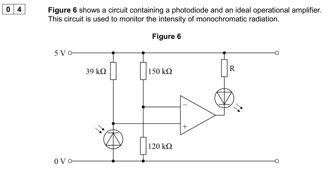
Q04.2
The whole paper ↗Q02.1
The whole paper ↗
Q04.4
The whole paper ↗
Q02.2
The whole paper ↗Q02.3
The whole paper ↗Q01.2
The whole paper ↗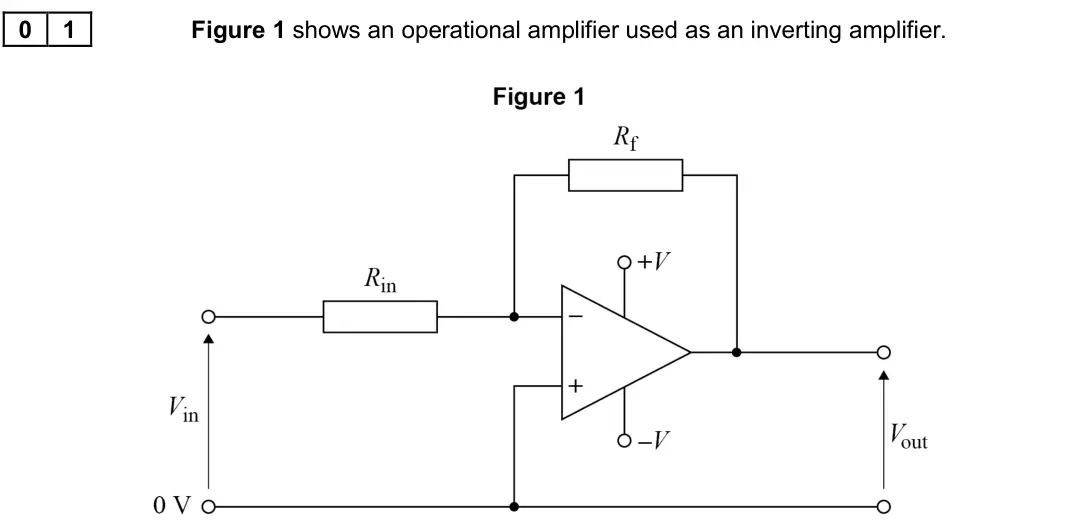
Q04.2
The whole paper ↗
Q4(a)
The whole paper ↗
All 11 questions on Non-inverting amplifier configuration, as a list
- June 2025, Paper 3 Electronics, Q02.3 (3 marks): Deduce the voltage V+ at the non-inverting input of the operational amplifier when: • the output voltage Vout is 0.0 V • the output voltage Vout is 9.0 V. [3 ma
- June 2025, Paper 3 Electronics, Q03.3 (2 marks): The output signal Vout from stage 1 is used as the input signal Vin for stage 2. Figure 9 is an incomplete circuit diagram of stage 2. Figure 9 Complete Figure
- November 2020, Paper 3 Electronics, Q04.1 (1 mark): What is the configuration of the operational amplifier circuit shown in Figure 6? Tick () one box. [1 mark] comparator differential amplifier inverting amplifi
- November 2020, Paper 3 Electronics, Q04.2 (3 marks): Figure 7 shows the variation of photocurrent with intensity for the monochromatic radiation incident on the photodiode. Figure 7 Radiation of intensity 3.0 W m−
- June 2019, Paper 3 Electronics, Q02.1 (1 mark): What is the operational amplifier configuration shown in Figure 4? Tick () one box. [1 mark] non-inverting amplifier comparator summing amplifier difference am
- June 2019, Paper 3 Electronics, Q04.4 (2 marks): The circuit in Figure 12 is rebuilt and the position of R is swapped with the position of the Zener diode. Explain how this affects the light intensity at which
- June 2018, Paper 3 Electronics, Q02.2 (2 marks): An operational amplifier in non-inverting mode is used to amplify the output of the sensor. The partially completed circuit diagram is shown in Figure 3. Figure
- June 2018, Paper 3 Electronics, Q02.3 (2 marks): Determine, using resistors selected from the list below, how the voltage gain of 40 can be achieved by the non-inverting amplifier of Figure 3. 1 kΩ 3.6 kΩ 10 k
- June 2017, Paper 3 Electronics, Q01.2 (1 mark): Name the input pin shown by a (+) on the operational amplifier. [1 mark]
- June 2017, Paper 3 Electronics, Q04.2 (1 mark): In which mode is the operational amplifier being used in Figure 10? Tick () the correct box. [1 mark] Non-inverting amplifier Comparator Summing amplifier Diff
- June 2008, PHA9W (2008 spec), Q4(a) (5 marks): 4 (a) Draw a non-inverting voltage amplifier circuit containing an operational amplifier. The amplifier circuit is required to have a voltage gain of +50. Give
Questions, mark schemes and examiner’s reports are © AQA, from their published past papers. Plumi isn’t affiliated with any exam board. Want whole papers? AQA A-Level Physics past papers.
The Plumi iPad app also offers exam-style questions with AI feedback on your handwritten working.