 plumi
LC resonance filters: AQA A‑Level Physics questions
AQA A-Level Physics past-paper questions on 3.13.3.1 LC resonance filters, 2008–2025, with mark schemes and examiner’s reports where available.
Paper
All papers
Exam
All years
Calculations
Q04.2
The whole paper ↗Q04.3
The whole paper ↗Q03.1
The whole paper ↗
Q03.2
The whole paper ↗Q02.1
The whole paper ↗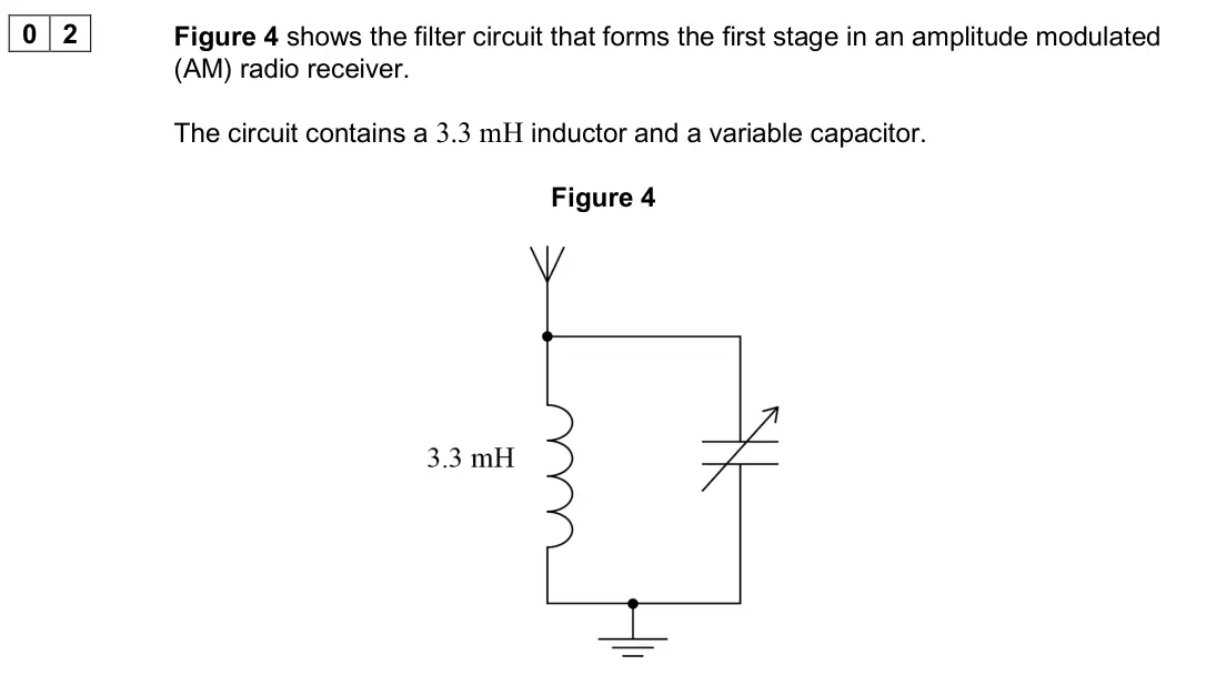
Q02.2
The whole paper ↗Q02.3
The whole paper ↗Q02.4
The whole paper ↗Q02.5
The whole paper ↗Q03.1
The whole paper ↗
Q03.2
The whole paper ↗Q03.3
The whole paper ↗Q04.1
The whole paper ↗
Q04.2
The whole paper ↗Q04.3
The whole paper ↗
All 15 questions on LC resonance filters, as a list
- June 2025, Paper 3 Electronics, Q04.2 (2 marks): Figure 12 shows the first stage of a radio receiver. Figure 12 Explain the role of the LC circuit in the first stage of the receiver. [2 marks]
- June 2025, Paper 3 Electronics, Q04.3 (2 marks): Two different LC circuits A and B are available for the first stage of a radio receiver tuned to a particular radio station. One of these circuits is to be chos
- June 2024, Paper 3 Electronics, Q03.1 (1 mark): Which quantity in the LC circuit is analogous to the mass in a mass–spring system? Tick () one box. [1 mark] C 1 C L 1 L
- June 2024, Paper 3 Electronics, Q03.2 (3 marks): A radio receiver uses a parallel LC tuned circuit to select a radio station. Figure 9 shows the response of the tuned circuit. Figure 9 Calculate the quality fa
- November 2020, Paper 3 Electronics, Q02.1 (1 mark): The circuit is tuned to receive a radio station transmitting at a frequency of 1053 kHz. Calculate the value of the capacitance needed to receive this station.
- November 2020, Paper 3 Electronics, Q02.2 (2 marks): The circuit is retuned to receive a different radio station by setting the variable capacitor to a value of 9.3 pF. Table 2 shows the capacitance range of four
- November 2020, Paper 3 Electronics, Q02.3 (2 marks): Figure 5 shows part of the frequency response curve for a different filter circuit. Figure 5 Determine the bandwidth of the filter circuit. [2 marks] bandwidth
- November 2020, Paper 3 Electronics, Q02.4 (1 mark): Calculate the Q factor of the filter circuit in Question 02.3. [1 mark] Q factor =
- November 2020, Paper 3 Electronics, Q02.5 (1 mark): The radio station is tuned using a different filter circuit with a very low Q factor. State and explain one effect of this change on the sound heard by a listen
- June 2017, Paper 3 Electronics, Q03.1 (2 marks): Calculate the value of the capacitance when the circuit resonates at a frequency of 910 kHz. [2 marks] capacitance = pF
- June 2017, Paper 3 Electronics, Q03.2 (3 marks): Draw on Figure 9 an ideal response curve for the resonant circuit, labelling all relevant frequency values based upon a 10 kHz bandwidth. [3 marks] Figure 9
- June 2017, Paper 3 Electronics, Q03.3 (2 marks): The Q-factor for the practical tuning circuit has a smaller value than the ideal one assumed in question 03.2. Discuss the changes the listener might notice whe
- Specimen, Paper 3 Electronics, Q04.1 (2 marks): An engineer uses copper cable to connect an intercom system between her office and workshop. The signals have to travel a long distance and she finds that inter
- Specimen, Paper 3 Electronics, Q04.2 (1 mark): An engineer uses copper cable to connect an intercom system between her office and workshop. The signals have to travel a long distance and she finds that inter
- Specimen, Paper 3 Electronics, Q04.3 (2 marks): An engineer uses copper cable to connect an intercom system between her office and workshop. The signals have to travel a long distance and she finds that inter
Questions, mark schemes and examiner’s reports are © AQA, from their published past papers. Plumi isn’t affiliated with any exam board. Want whole papers? AQA A-Level Physics past papers.
The Plumi iPad app also offers exam-style questions with AI feedback on your handwritten working.