 plumi
Electromagnetic induction and generators: OCR A‑Level Physics B questions
OCR A-Level Physics B past-paper questions on 6.1.1.2 Electromagnetic induction and generators, 2016–2025, with mark schemes and examiner’s reports where available.
Paper
All papers
Exam
All years
Calculations
- Your answer
Q8(b)
The whole paper ↗- Your answer
Q7(a)(i)
The whole paper ↗
Q7(a)(ii)
The whole paper ↗Q7(b)
The whole paper ↗Q4(a)(i)
The whole paper ↗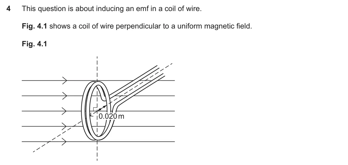
Q4(a)(ii)
The whole paper ↗Q4(a)(iii)
The whole paper ↗Q4(a)(iv)
The whole paper ↗Q4(b)(i)
The whole paper ↗Q4(b)(ii)
The whole paper ↗Q4(b)(iii)
The whole paper ↗Q2(a)(i)
The whole paper ↗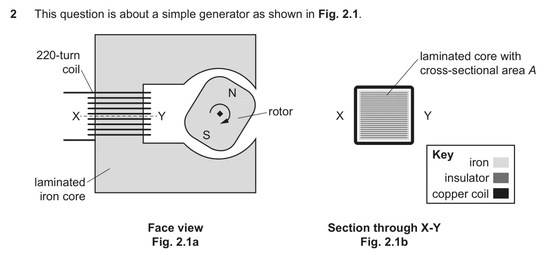
Q2(b)(i)
The whole paper ↗Q2(b)(ii)
The whole paper ↗Q5(e)
The whole paper ↗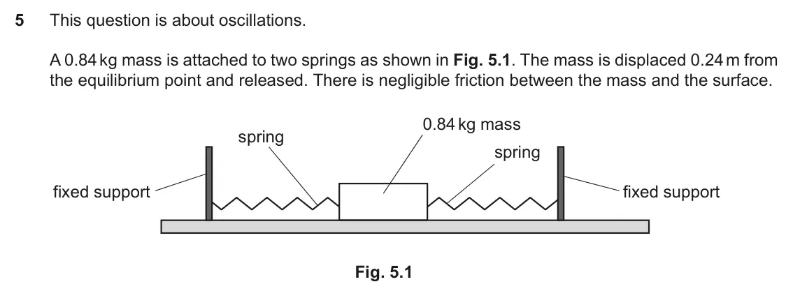
- Your answer
- Your answer
All 27 questions on Electromagnetic induction and generators, as a list
- June 2025, Paper 1, Q22 (1 mark): The graph shows how the flux linkage for a coil rotating in a magnetic field varies with time. N Φ 0 t 0 Which graph shows how the induced e.m.f. ε in the coil
- June 2025, Paper 2, Q8(b) (2 marks): Fig. 8 shows how the flux through a coil of 170 turns in a dynamic microphone oscillating in a magnetic field changes with time. Fig. 8 1.25 / μWb 1.00 0.75 0.5
- June 2025, Paper 2, Q10 (6 marks): 10* Using appropriate equations, explain and compare how the phase of the output signal from dynamic and condenser microphones relates to the phase of the incid
- June 2024, Paper 1, Q14 (1 mark): The diagram shows a circular coil with its plane parallel to a uniform magnetic field. R uniform P Q magnetic T field S The coil can move in three ways within t
- June 2023, Paper 2, Q7(a)(i) (2 marks): Calculate the maximum flux linkage in the coil. maximum flux linkage = Wb turns [2]
- June 2023, Paper 2, Q7(a)(ii) (2 marks): The coil has sides of length 12 cm. It has 400 turns. Calculate the flux density B of the magnetic field. flux density B = T [2]
- June 2023, Paper 2, Q7(b) (4 marks): Suggest and explain two modifications to the generator that would increase the e.m.f. induced without changing the frequency of the rotor. You may refer to equa
- June 2023, Paper 3, Q4(a)(i) (2 marks): The coil has 10 turns of radius 0.020 m. The field strength is 5.0 mT. Show that the flux linkage of the coil is about 6.3 × 10⁻⁵ Wb. [2] The coil is rotated at
- June 2023, Paper 3, Q4(a)(ii) (2 marks): Suggest and explain why the trace has the shape shown on Fig. 4.3. [2]
- June 2023, Paper 3, Q4(a)(iii) (3 marks): The horizontal divisions on the trace representing time are set at 0.625 s/div. Using the trace shown in Fig. 4.3, calculate the angular frequency, ω, of the co
- June 2023, Paper 3, Q4(a)(iv) (2 marks): The angle θ, that the normal to the plane of the coil makes with the field lines varies with time as the coil rotates. Angle θ is shown in Fig. 4.4. Fig. 4.4 θ
- June 2023, Paper 3, Q4(b)(i) (2 marks): Add to Fig. 4.5 a drawing of the trace produced by the 20-turn coil. [2] 16 The driving force spinning the coil is removed. Fig. 4.6 shows how the flux linkage
- June 2023, Paper 3, Q4(b)(ii) (3 marks): Using the graph in Fig. 4.6, estimate the emf induced in the coil at the instant the flux linkage is zero at 0.23 s. Show all your working. emf = V [3]
- June 2023, Paper 3, Q4(b)(iii) (6 marks): This question is about inducing an emf in a coil of wire. Fig. 4.1 shows a coil of wire perpendicular to a uniform magnetic field. Fig. 4.1 0.020 m 0.020 m (iii
- June 2022, Paper 2, Q2(a)(i) (4 marks): The core is made of sheets of iron which have been laminated (separated by thin sheets of electrically insulating material). The layers of iron and insulator ar
- June 2022, Paper 2, Q2(b)(i) (3 marks): The cross-sectional area A of the iron core inside the coil is 1.5 × 10⁻⁴ m2. Explain, without calculation, how the maximum emf across the 220-turn coil can be
- June 2022, Paper 2, Q2(b)(ii) (2 marks): The emf ε across each turn of the coil is given by the equation ε = 2πfφmaxsin 2πft Use the equation and data from Fig. 2.2 and part (b) (i) to calculate the ma
- November 2021, Paper 2, Q5(e) (4 marks): A powerful magnet is fixed to the side of the mass as shown in Fig. 5.2. An aluminium sheet is placed below the mass. The friction between the mass and the meta
- November 2020, Paper 1, Q25 (1 mark): The input current I to a simple transformer varies with time t as shown in the graph. I / A 0 t / s A B C D At which point in time A, B, C or D shown on the gra
- November 2020, Paper 1, Q29 (1 mark): Which is the best estimate of the e.m.f. induced across the plane’s wingtips? A 240 mV B 650 mV C 740 mV D 2030 mV Your answer [1]
- November 2020, Paper 1, Q30 (1 mark): For horizontal flight at the position shown, in which direction should the plane fly to experience maximum induced e.m.f. from the Earth’s magnetic field? A All
- November 2020, Paper 3, Q4(d)(i) (3 marks): Estimate the maximum flux through the secondary coil. maximum flux = Wb [3] 17 The student now uses a different set of C-cores which have a greater overall leng
- June 2019, Paper 1, Q24 (1 mark): The graph shows how the flux linkage N Φ through a coil changes with time when the coil is moved into a magnetic field. N Φ 0 0 t0 time Which of the following g
- June 2019, Paper 2, Q3(a) (4 marks): A bar magnet is dropped through a vertically mounted coil connected to a data-logger, as shown in Fig. 3.1. S to data-logger magnet N coil Fig. 3.1 The e.m.f. r
- June 2019, Paper 2, Q3(b) (4 marks): An aluminium disk, mounted horizontally on a low-friction pivot, is placed between the poles of a strong magnet, as shown in Fig. 3.3. There is a uniform magnet
- June 2018, Paper 1, Q40(b) (6 marks): Fig. 40.1 shows a simplified diagram of a d.c. motor with permanent magnets. Fig. 40.2 shows the graph of current in the coil against frequency of rotation for
- June 2017, Paper 1, Q22 (1 mark): An aluminium ring is free to move on a steel rod. When the power supply is on, the ring floats. steel rod aluminium ring power floating above supply the coil co
Questions, mark schemes and examiner’s reports are © OCR, from their published past papers. Plumi isn’t affiliated with any exam board. Want whole papers? OCR A-Level Physics B past papers.
The Plumi iPad app also offers exam-style questions with AI feedback on your handwritten working.