 plumi
Sequential logic: AQA A‑Level Physics questions
AQA A-Level Physics past-paper questions on 3.13.5.2 Sequential logic, 2008–2025, with mark schemes and examiner’s reports where available.
Paper
All papers
Exam
All years
Calculations
Q01.1
The whole paper ↗Q01.4
The whole paper ↗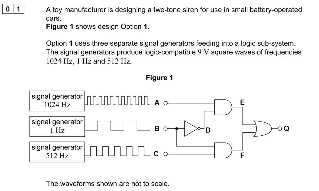
Q01.1
The whole paper ↗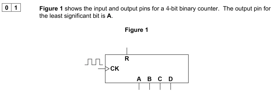
Q04.1
The whole paper ↗
Q04.3
The whole paper ↗Q01.1
The whole paper ↗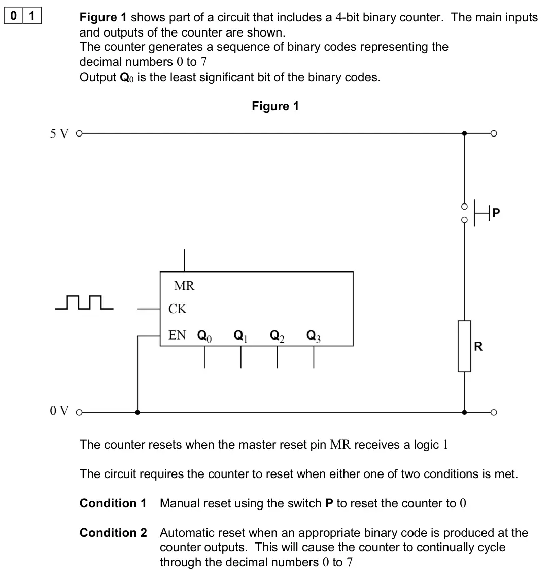
Q01.1
The whole paper ↗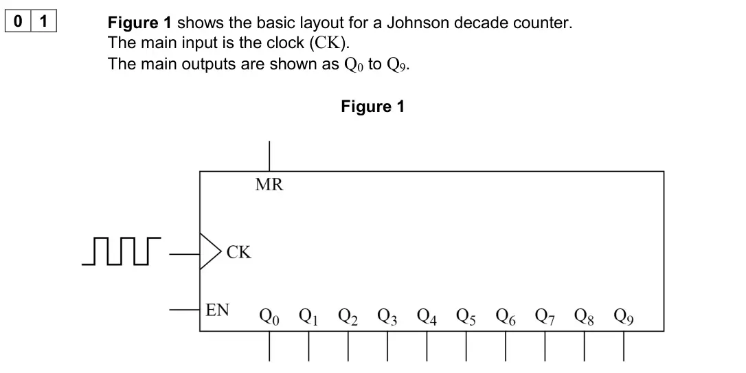
Q01.2
The whole paper ↗Q01.3
The whole paper ↗Q02.3
The whole paper ↗
All 10 questions on Sequential logic, as a list
- June 2025, Paper 3 Electronics, Q01.1 (5 marks): Figure 1 shows a system diagram for a timer designed by a student. Figure 1 The system displays the numbers from 00 to 59 before resetting. The timer is designe
- June 2024, Paper 3 Electronics, Q01.4 (1 mark): Figure 4 shows a generalised layout of an integrated circuit (IC) for an N-bit binary counter. Q0 is the output that provides the least significant bit. Figure
- June 2023, Paper 3 Electronics, Q01.1 (2 marks): Complete Figure 1 by adding a single logic gate to the binary counter so that the circuit functions as a modulo-6 counter. [2 marks] Figure 2 shows three output
- November 2021, Paper 3 Electronics, Q04.1 (2 marks): Describe one functional difference and one functional similarity between how a Johnson decade counter and a BCD counter output their counts. [2 marks] functiona
- November 2021, Paper 3 Electronics, Q04.3 (2 marks): The astable is adjusted to produce a 600 Hz test signal. This signal is applied to the clock input of the BCD counter and to the clock input of the Johnson deca
- November 2020, Paper 3 Electronics, Q01.1 (3 marks): Complete Figure 1 to show how both reset conditions can be met. Do not show the power line connections to the integrated circuit. [3 marks]
- June 2019, Paper 3 Electronics, Q01.1 (2 marks): Figure 2 shows part of the timing diagram for a Johnson decade counter. This timing diagram shows the output logic states against time. The counter is reset to
- June 2019, Paper 3 Electronics, Q01.2 (1 mark): A student sets up the counter to make the traffic light sequence: red → red + amber → green → amber The sequence then repeats. Figure 3 shows a partially comple
- June 2019, Paper 3 Electronics, Q01.3 (2 marks): State two factors that determine the ON time for the green LED shown in Figure 3. [2 marks] 1 2
- June 2017, Paper 3 Electronics, Q02.3 (2 marks): Figure 6 shows some of the input and output pins of the 4-bit binary counter. The data sheet for the counter indicates that the counter resets when the reset pi
Questions, mark schemes and examiner’s reports are © AQA, from their published past papers. Plumi isn’t affiliated with any exam board. Want whole papers? AQA A-Level Physics past papers.
The Plumi iPad app also offers exam-style questions with AI feedback on your handwritten working.