 plumi
Logic gates: AQA A‑Level Computer Science questions
Every AQA A-Level Computer Science exam question on 4.6.4 Logic gates, 2020–2025, with its mark scheme and examiner’s report.
Find questions561
Calculations
Q09.1
The whole paper ↗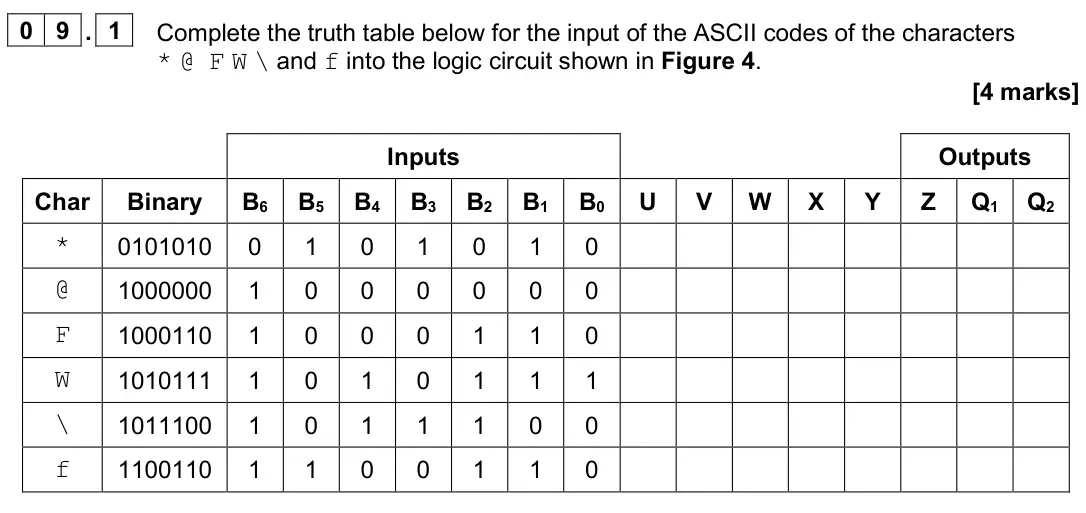
Q09.2
The whole paper ↗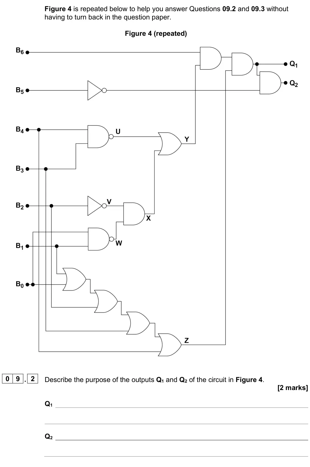
Q09.3
The whole paper ↗
Q07.1
The whole paper ↗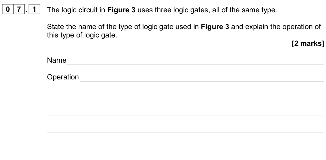
Q07.2
The whole paper ↗
Q08.2
The whole paper ↗
Q06.1
The whole paper ↗
Q06.2
The whole paper ↗
Q06.1
The whole paper ↗
Q06.2
The whole paper ↗
Q06.3
The whole paper ↗
Q09.1
The whole paper ↗
Q09.2
The whole paper ↗
Q07.1
The whole paper ↗
Q07.2
The whole paper ↗
Q07.1
The whole paper ↗
Q07.2
The whole paper ↗
Q07.3
The whole paper ↗
Q07.4
The whole paper ↗
Q04.1
The whole paper ↗
All 28 questions on Logic gates, as a list
- June 2025, Paper 2, Q09.1 (4 marks): Complete the truth table below for t
- June 2025, Paper 2, Q09.2 (2 marks): 0 9 Figure 4 shows a logic circuit. The circuit has seven inputs and two outputs. The inputs B6 to B0 represent the ASCII code of a character, where B6 is the m
- June 2025, Paper 2, Q09.3 (1 mark): Shade one lozenge to indicate which
- June 2025, AS Paper 2, Q07.1 (2 marks): The logic circuit in Figure 3 uses three logic gates, all of the same type. State the name of the type of logic gate used in Figure 3 and explain the operation
- June 2025, AS Paper 2, Q07.2 (2 marks): State the type of parity that is computed by the logic circuit in Figure 3 and give a reason for your answer. [2 marks] Type of parity Reason
- June 2025, AS Paper 2, Q08.2 (3 marks): Draw a logic circuit for the Boolean expression below using only AND, OR and NOT gates. [3 marks] Q = X + Y + (Z ⋅Y) + X
- June 2024, Paper 2, Q06.1 (4 marks): Draw a logic circuit for the Boolean expression: Q = A B+ B+ C D ⋅ ⋅ Do not simplify the expression. [4 marks]
- June 2024, Paper 2, Q06.2 (1 mark): A flip-flop is a component that can be incorporated into a logic circuit. Figure 3 shows a diagram of an edge-triggered D-type flip-flop. Figure 3 Explain how t
- June 2024, AS Paper 2, Q06.1 (1 mark): Figure 2 shows the symbol for a logic gate. Figure 2 State the name of the logic gate shown in Figure 2. [1 mark]
- June 2024, AS Paper 2, Q06.2 (2 marks): Figure 3 shows a logic circuit. Figure 3 Complete the truth table for the logic circuit in Figure 3. [2 marks] A B C L M Z 0 0 0 0 0 1 0 1 0 0 1 1 1 0 0 1 0 1 1
- June 2024, AS Paper 2, Q06.3 (3 marks): Figure 4 shows a logic circuit. Figure 4 Write a Boolean expression for Q. [3 marks]
- June 2023, Paper 2, Q09.1 (3 marks): In the space below, draw a logic circuit that would produce the outputs shown in Table 4 for the given inputs. To achieve full marks for your response, your cir
- June 2023, Paper 2, Q09.2 (1 mark): Explain the purpose of the circuit that you have drawn that produces the outputs given in Table 4. [1 mark]
- June 2023, AS Paper 2, Q07.1 (3 marks): Figure 3 shows a circuit diagram. Figure 3 Complete the truth table below for the circuit shown in Figure 3. [3 marks] A B C L M N X Y 0 0 0 0 0 0 0 1 0 1 0 1 0
- June 2023, AS Paper 2, Q07.2 (2 marks): Using Figure 3, write a Boolean expression for output Y in terms of inputs A, B and C. [2 marks] Y =
- June 2022, AS Paper 2, Q07.1 (1 mark): State which logic gate has the truth table shown in Figure 4. [1 mark] Figure 4 A B Q 0 0 1 0 1 0 1 0 0 1 1 0 Answer
- June 2022, AS Paper 2, Q07.2 (1 mark): State the logic gate that is represented by the symbol shown in Figure 5. [1 mark] Figure 5 Answer
- June 2022, AS Paper 2, Q07.3 (2 marks): Draw the logic circuit for the following Boolean expression. = + Q A B C [2 marks]
- June 2022, AS Paper 2, Q07.4 (3 marks): Complete the truth table below. A B B + A B + A B B 0 0 0 1 1 0 1 1 Using the final column, give a simplified Boolean expression for ( ) + A B B [3 marks] Answe
- November 2021, Paper 2, Q04.1 (1 mark): Write a Boolean expression to represent the output Q1 of the circuit in Figure 1. [1 mark] Q1 =
- November 2021, Paper 2, Q04.2 (3 marks): Complete the truth table below for the circuit in Figure 1. [3 marks] INPUTS OUTPUTS X2 X1 X0 Q0 Q1 Q2 Q3 Q4 Q5 Q6 Q7 0 0 0 0 0 1 0 1 0 0 1 1 1 0 0 1 0 1 1 1 0
- November 2021, Paper 2, Q04.3 (2 marks): Explain the purpose of the circuit in Figure 1. Considering the inputs and outputs of the circuit and consulting your answers to Question 04.1 and Question 04.2
- November 2021, Paper 2, Q04.4 (1 mark): The logic circuit in Figure 2 produces an output S that is equivalent to one of the outputs of the logic circuit in Figure 1, for the inputs X0, X1 and X2. Figu
- November 2020, Paper 2, Q06.1 (1 mark): Figure 6 shows truth tables for four logic gates. The truth tables are labelled Table A, Table B, Table C and Table D. Figure 6 Table A Table B Table C Table D
- November 2020, Paper 2, Q06.2 (4 marks): Complete every empty cell in the truth table below for the circuit in Figure 7 • The listed inputs to the table (X3, X2, X1, X0) represent the decimal digits 0–
- November 2020, Paper 2, Q06.3 (1 mark): By considering the inputs and outputs of the circuit in Figure 7 and consulting your trace table, state which of the segments in the display (labelled a to g be
- November 2020, AS Paper 2, Q05.1 (1 mark): Complete the truth table for A NAND B. [1 mark] A B A NAND B 0 0 0 1 1 0 1 1
- November 2020, AS Paper 2, Q05.2 (3 marks): A XOR B can be implemented as a logic circuit without using an XOR gate. Using only AND, OR and NOT gates draw a circuit that will produce an output Q which is
Questions, mark schemes and examiner’s reports are © AQA, from their published past papers. Plumi isn’t affiliated with any exam board. Want whole papers? Full past papers.
Rather write your answers by hand on iPad? Plumi marks them against the same mark schemes.