 plumi
Current electricity: AQA A‑Level Physics questions
Every AQA A-Level Physics exam question on 3.5.1 Current electricity, 2016–2025, with its mark scheme and examiner’s report.
Find questions2,714
Calculations
Q05.1
The whole paper ↗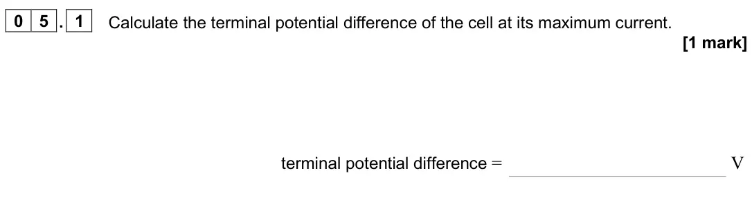
Q05.2
The whole paper ↗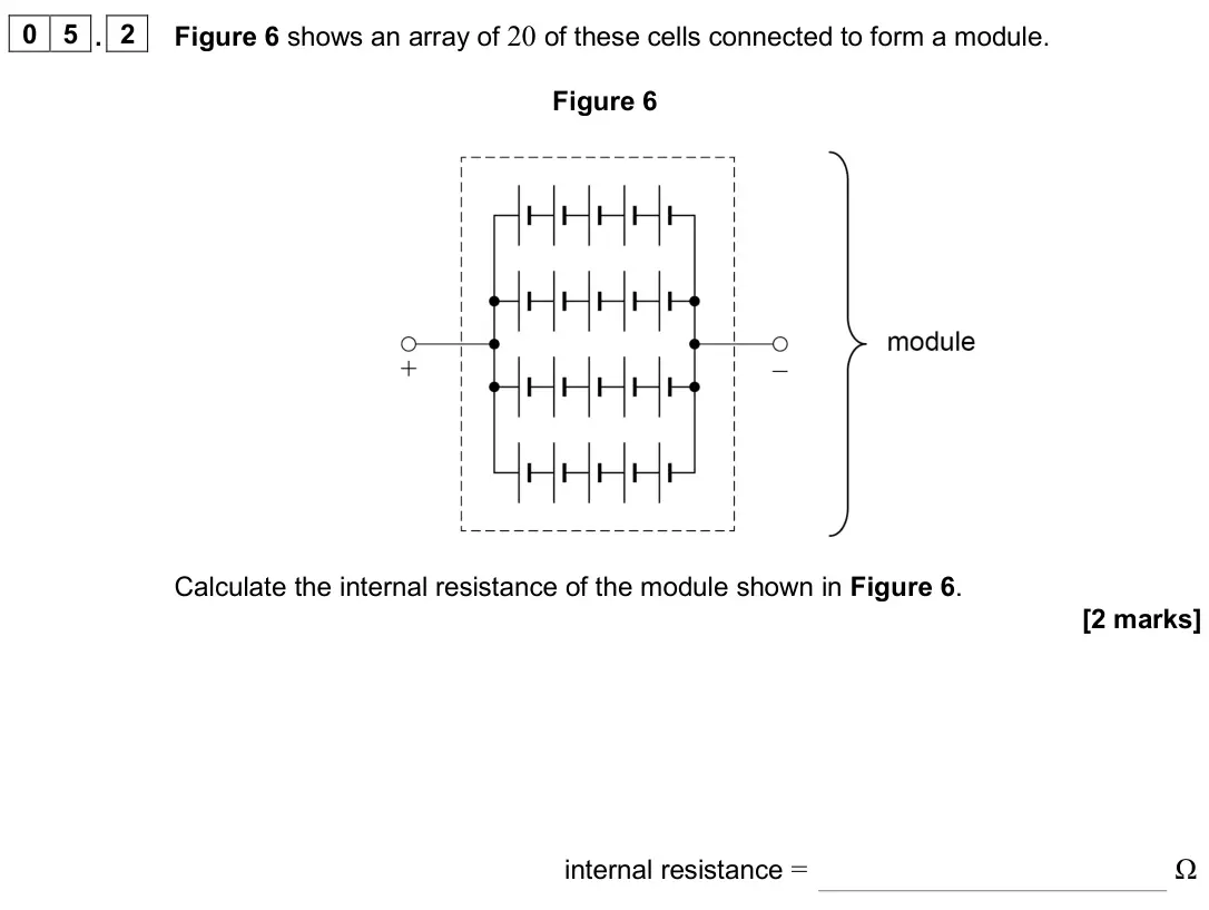
Q05.3
The whole paper ↗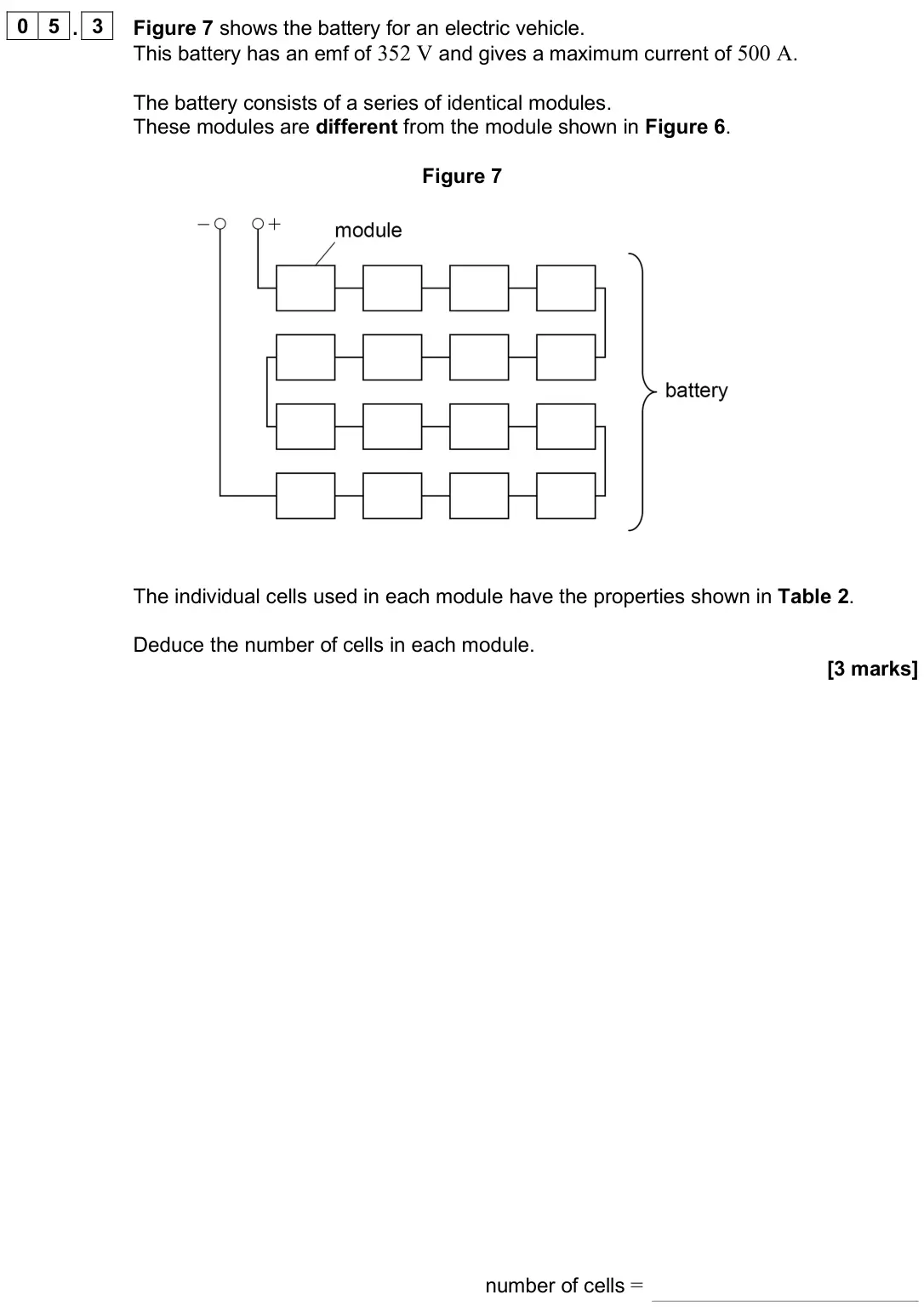
Q08.2
The whole paper ↗
Q03.1
The whole paper ↗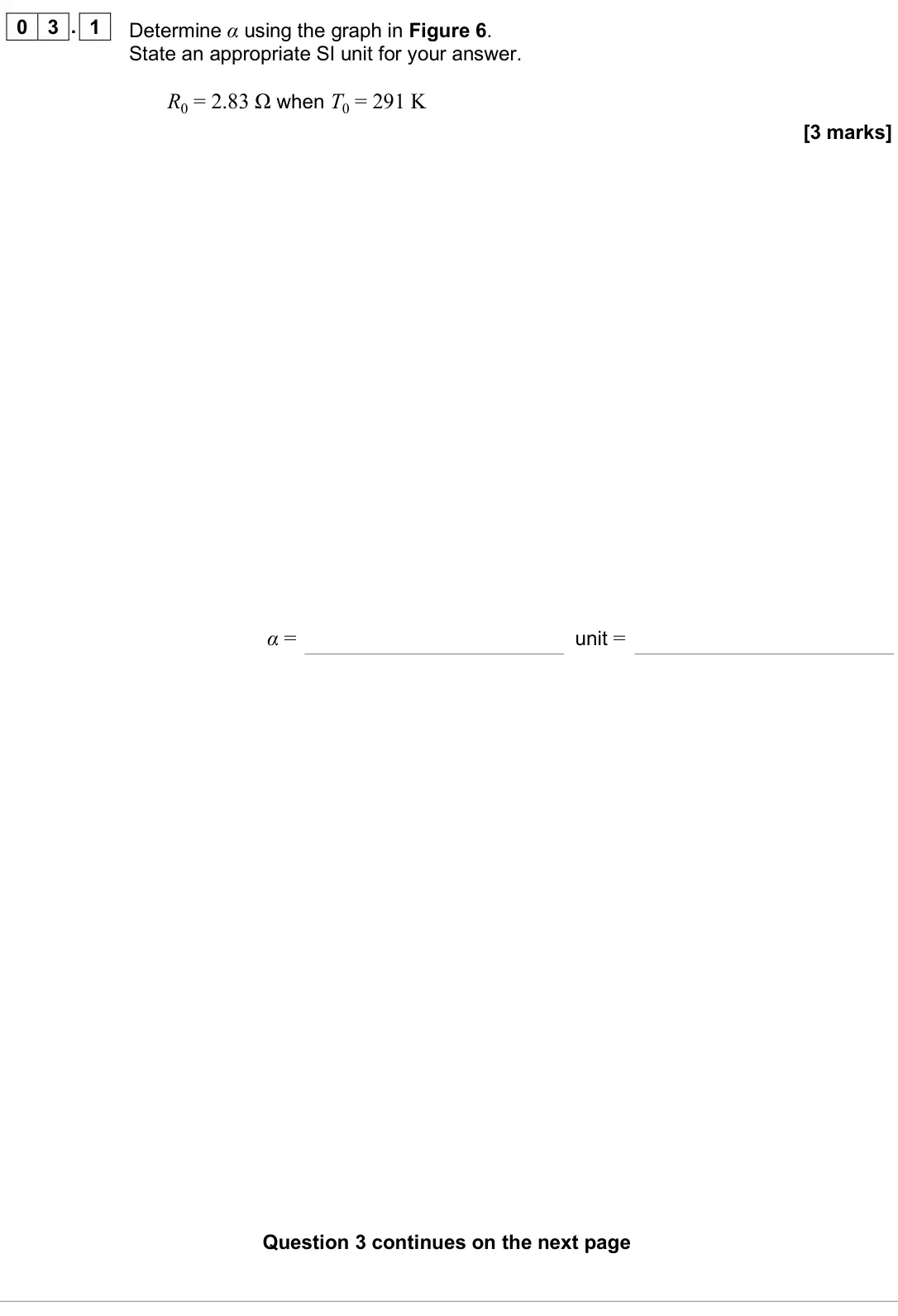
Q03.2
The whole paper ↗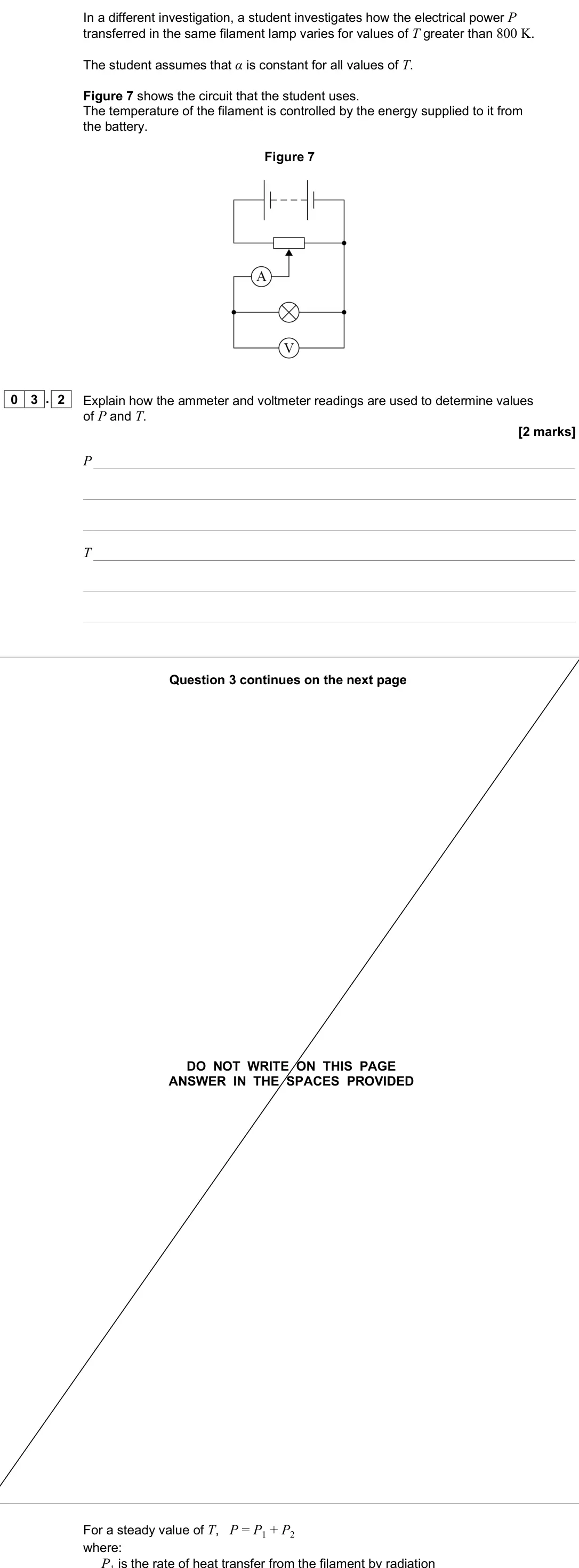
Q03.3
The whole paper ↗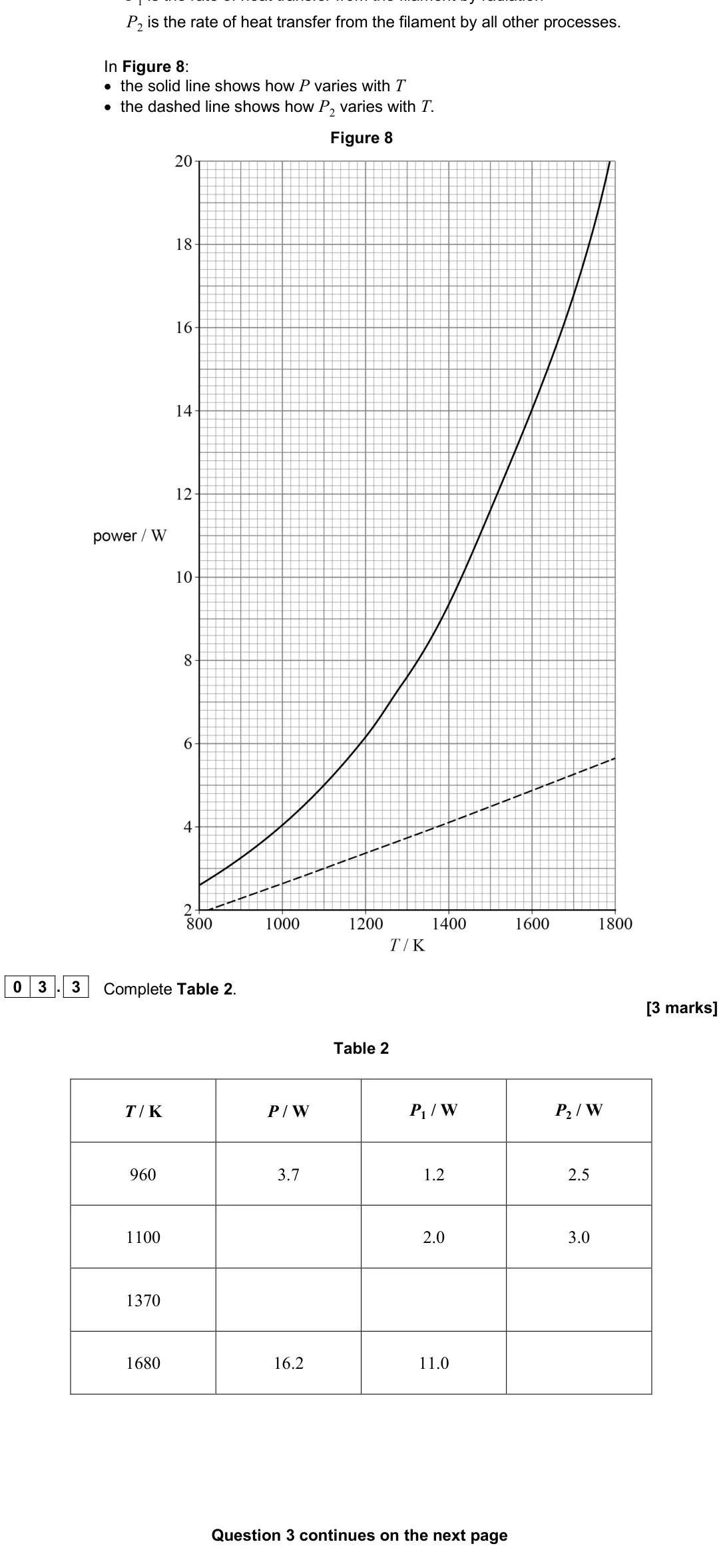
Q03.4
The whole paper ↗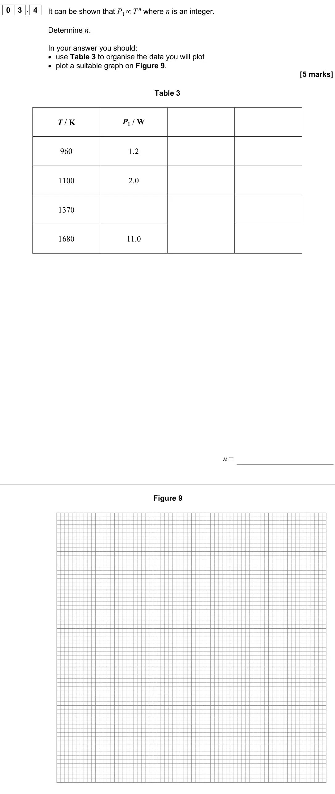
Q06.1
The whole paper ↗
Q06.2
The whole paper ↗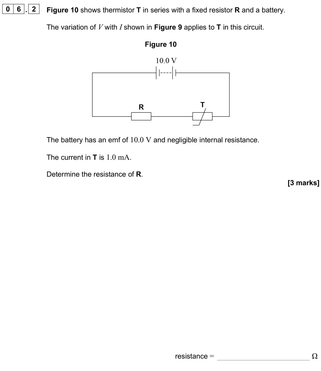
Q03.1
The whole paper ↗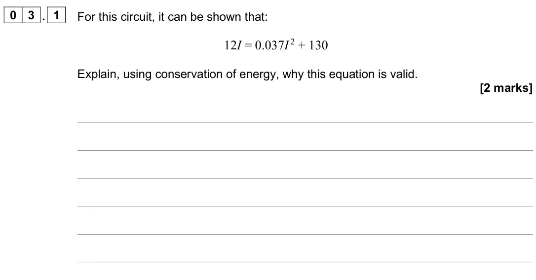
Q03.2
The whole paper ↗
Q03.3
The whole paper ↗
Q03.4
The whole paper ↗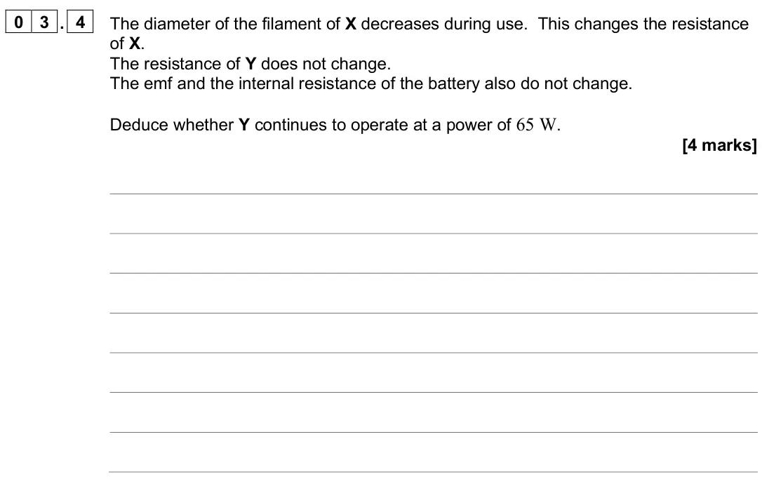
All 255 questions on Current electricity, as a list
- June 2025, Paper 1, Q05.1 (1 mark): Calculate the terminal potential difference of the cell at its maximum current. [1 mark] terminal potential difference = V
- June 2025, Paper 1, Q05.2 (2 marks): Figure 6 shows an array of 20 of these cells connected to form a module. Figure 6 Calculate the internal resistance of the module shown in Figure 6. [2 marks] i
- June 2025, Paper 1, Q05.3 (3 marks): Figure 7 shows the battery for an electric vehicle. This battery has an emf of 352 V and gives a maximum current of 500 A. The battery consists of a series of i
- June 2025, Paper 1, Q08.2 (1 mark): Explain why the average speed of the electrons in the tube is much less than the maximum speed you calculated in Question 08.1. [1 mark]
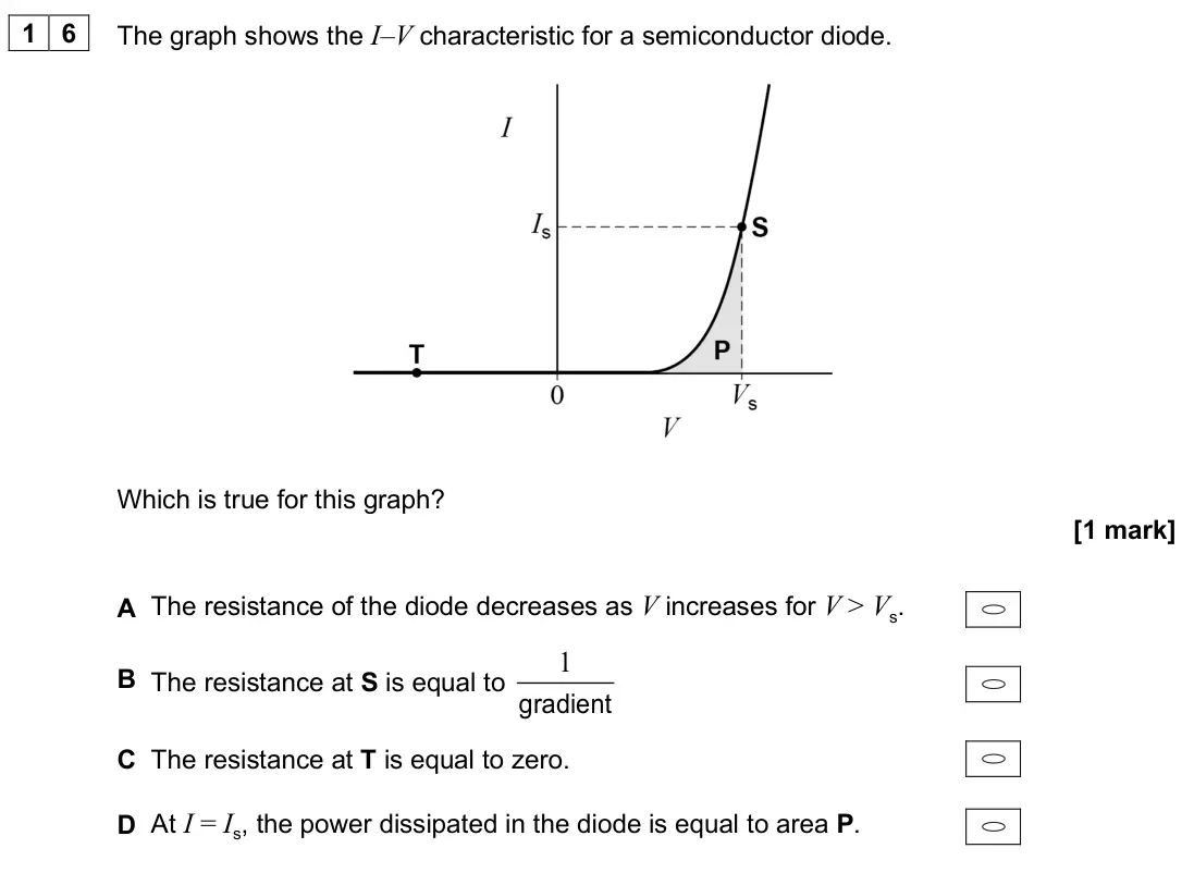
- June 2025, Paper 1, Q16 (1 mark): The graph shows the I–V characteristic for a semiconductor diode. Which is true for this graph? [1 mark] A The resistance of the diode decreases as V increases
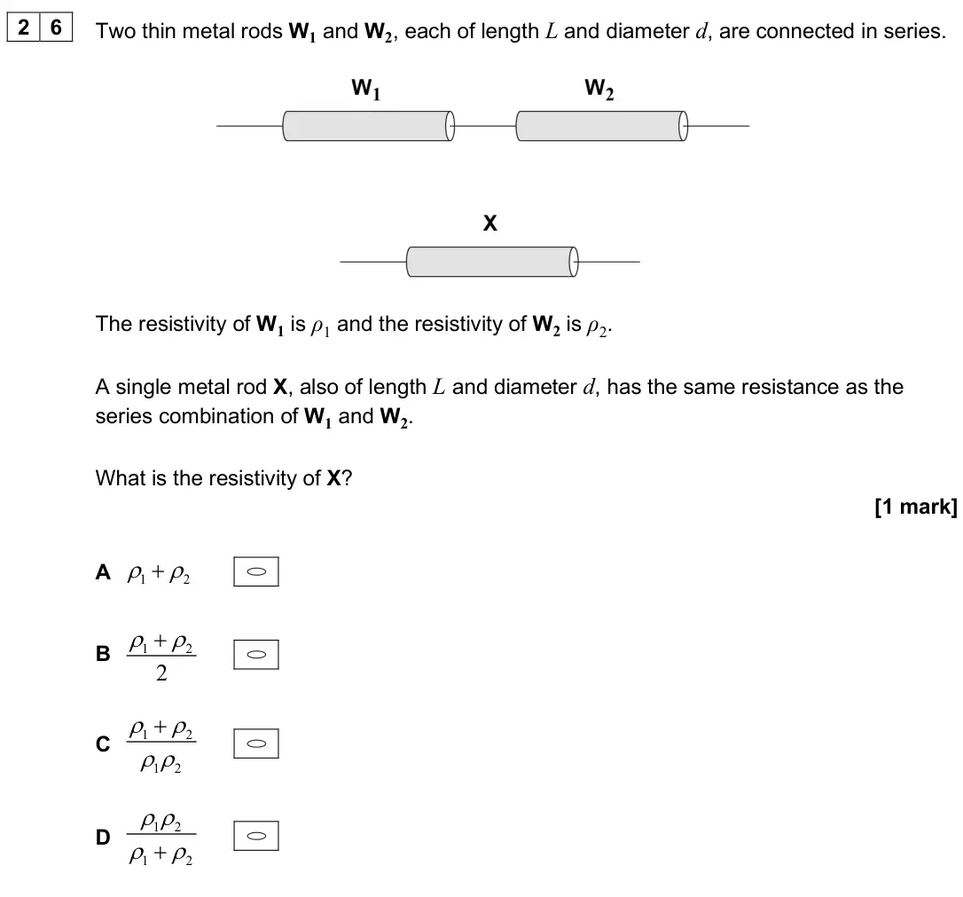
- June 2025, Paper 1, Q26 (1 mark): Two thin metal rods W1 and W2, each of length L and diameter d, are connected in series. The resistivity of W1 is ρ1 and the resistivity of W2 is ρ2. A single m
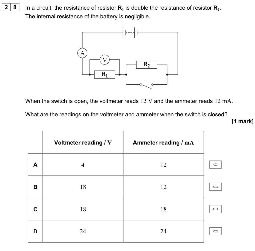
- June 2025, Paper 1, Q28 (1 mark): In a circuit, the resistance of resistor R1 is double the resistance of resistor R2. The internal resistance of the battery is negligible. When the switch is op
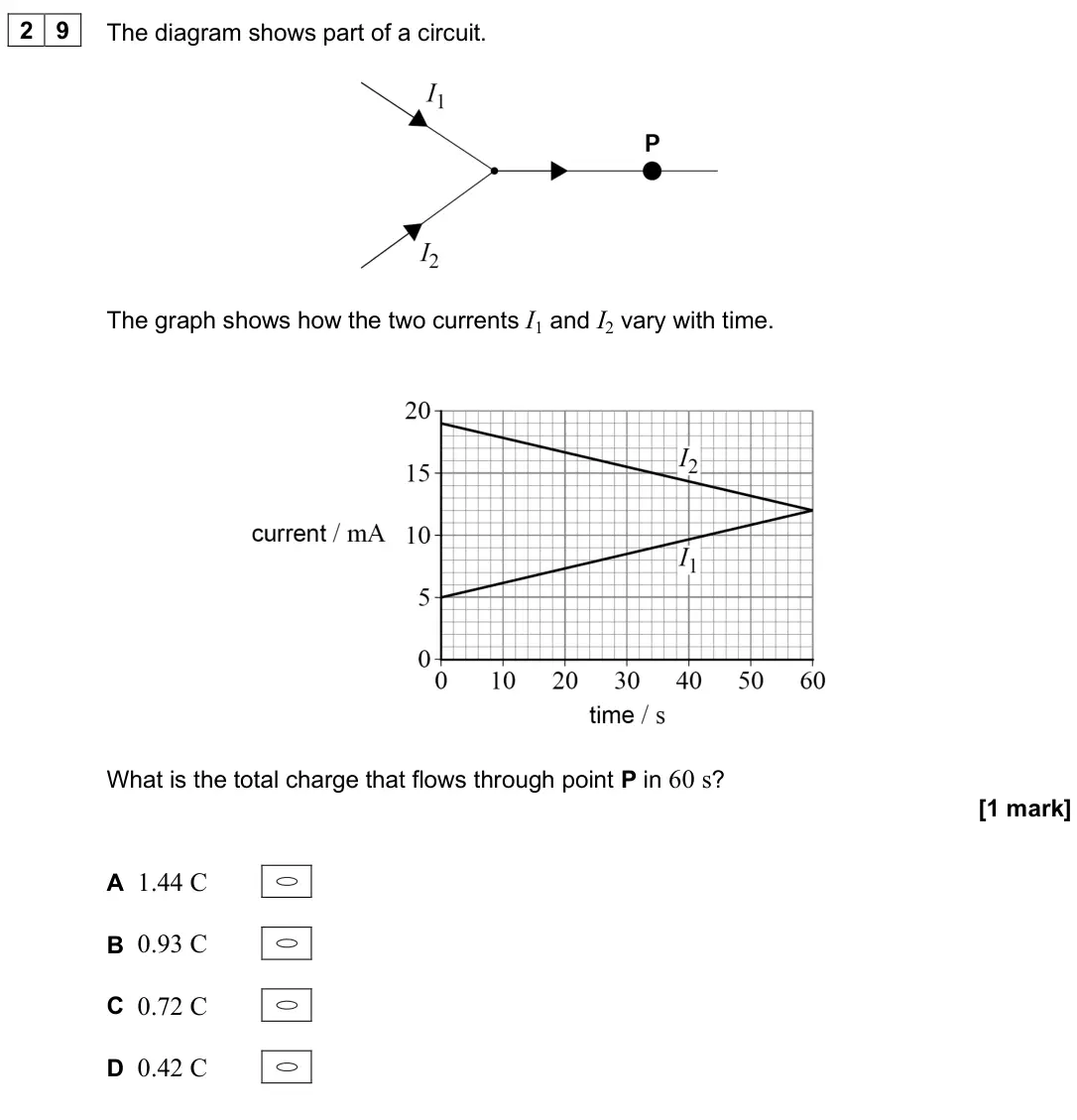
- June 2025, Paper 1, Q29 (1 mark): The diagram shows part of a circuit. The graph shows how the two currents I1 and I2 vary with time. What is the total charge that flows through point P in 60 s?
- June 2025, Paper 3A, Q03.1 (3 marks): Determine α using the graph in Figure 6. State an appropriate SI unit for your answer. R0 = 2.83 Ω when T0 = 291 K [3 marks] α = unit =
- June 2025, Paper 3A, Q03.2 (2 marks): Explain how the ammeter and voltmeter readings are used to determine values of P and T. [2 marks] P T DO NOT WRITE ON THIS PAGE ANSWER IN THE SPACES PROVIDED Fo
- June 2025, Paper 3A, Q03.3 (3 marks): Complete Table 2. [3 marks] Table 2 T / K P / W P1 / W P2 / W 960 3.7 1.2 2.5 1100 2.0 3.0 1370 1680 16.2 11.0
- June 2025, Paper 3A, Q03.4 (5 marks): It can be shown that P1∝T n where n is an integer. Determine n. In your answer you should: • use Table 3 to organise the data you will plot • plot a suitable gr
- June 2025, AS Paper 1, Q06.1 (6 marks): Discuss, for the range 0 to 9 mA, the characteristic of T shown by Figure 9. In your answer you should: • describe how to produce a characteristic experimentall
- June 2025, AS Paper 1, Q06.2 (3 marks): Figure 10 shows thermistor T in series with a fixed resistor R and a battery. The variation of V with I shown in Figure 9 applies to T in this circuit. Figure 1
- June 2025, AS Paper 2, Q03.1 (2 marks): For this circuit, it can be shown that: 12I = 0.037I 2 + 130 Explain, using conservation of energy, why this equation is valid. [2 marks]
- June 2025, AS Paper 2, Q03.2 (2 marks): Show that I is approximately 11 A. [2 marks]
- June 2025, AS Paper 2, Q03.3 (2 marks): Determine the resistance of X when it operates at a power of 65 W. [2 marks] resistance of X = Ω
- June 2025, AS Paper 2, Q03.4 (4 marks): The diameter of the filament of X decreases during use. This changes the resistance of X. The resistance of Y does not change. The emf and the internal resistan
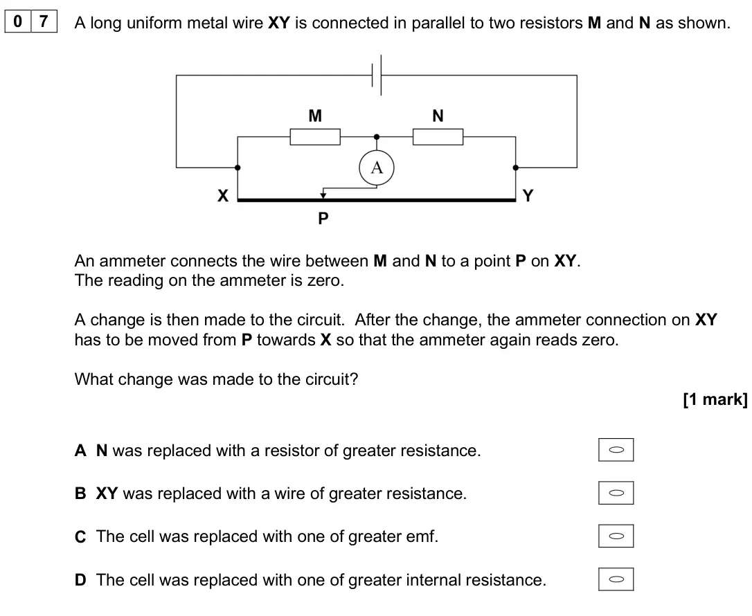
- June 2025, AS Paper 2, Q07 (1 mark): A long uniform metal wire XY is connected in parallel to two resistors M and N as shown. An ammeter connects the wire between M and N to a point P on XY. The re
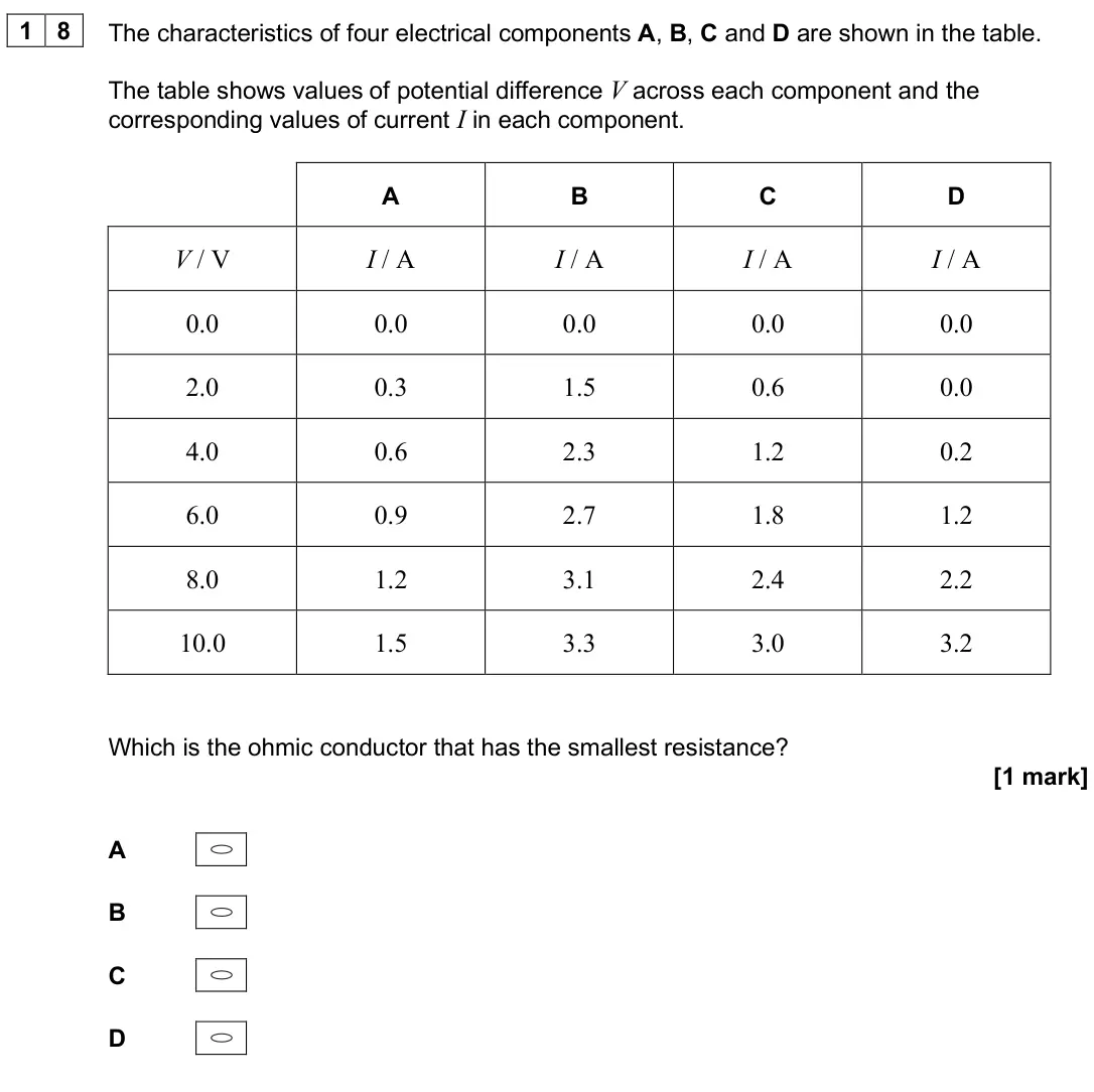
- June 2025, AS Paper 2, Q18 (1 mark): The characteristics of four electrical components A, B, C and D are shown in the table. The table shows values of potential difference V across each component a
- June 2025, AS Paper 2, Q26 (1 mark): The diagram shows the currents in a set of wires. What is the current in wire W? [1 mark] A 1 A B 2 A C 5 A D 7 A
- June 2025, AS Paper 2, Q30 (1 mark): A cell of negligible internal resistance is connected in parallel to a 20 Ω resistor and a resistor R. The emf of the cell is 6.0 V. The current in the cell is
- June 2025, AS Paper 2, Q33 (1 mark): A battery with negligible internal resistance is connected to a resistor of resistance 2.0 kΩ. The current in the battery is 6.0 mA. A non-ideal voltmeter is th
- June 2024, Paper 1, Q06.1 (2 marks): Calculate the resistance of the variable resistor. [2 marks] resistance = Ω
- June 2024, Paper 1, Q06.2 (5 marks): The resistance R of the thermistor at temperature θ in K is given by: 0 0 1 1 = e B R R − where R0 is the resistance at the initial temperature
- June 2024, Paper 1, Q06.3 (2 marks): Explain why the current in the thermistor needs to be controlled. [2 marks]
- June 2024, Paper 1, Q06.4 (2 marks): Explain how ammeters and voltmeters can be used in the circuit in Figure 5 to demonstrate the conservation of charge and the conservation of energy. Refer to po
- June 2024, Paper 1, Q27 (1 mark): A 12 Ω resistor is connected across the terminals of a battery of emf 2.0 V and internal resistance 4.0 Ω. What is the pd across the resistor? [1 mark] A 0.25 V
- June 2024, Paper 3A, Q01.4 (2 marks): When the switch is closed, the voltmeter reading is 397 mV. Show that, for the arrangement in Figure 4, the resistance R of the wire between the clips is about
- June 2024, Paper 3A, Q01.5 (2 marks): Determine the resistance per metre of X. [2 marks] resistance per metre = Ω m−1
- June 2024, Paper 3A, Q01.6 (4 marks): Table 1 shows the resistance per metre of various metal wires. The diameter of X is one of the values of d shown in Table 1. Table 1 Resistance per metre of wir
- June 2024, Paper 3A, Q02.1 (1 mark): Explain why the reading displayed in Figure 6 shows that the ohm-meter is set to range C. [1 mark]
- June 2024, Paper 3A, Q02.2 (2 marks): The quantity EV is a measure of the intensity of the light incident on the LDR. The SI unit of EV is the lux (lx). The resistance R of the LDR is given by log(R
- June 2024, Paper 3A, Q02.3 (2 marks): Describe a method to show that Figure 7 confirms this relationship. You do not need to show any calculations. [2 marks]
- June 2024, Paper 3A, Q02.4 (2 marks): Deduce the value of x when EV = 130 lx. [2 marks] x = mm
- June 2024, Paper 3A, Q02.6 (2 marks): The positions of the lamp and the LDR are not changed during the experiment. Identify two other control variables. [2 marks] 1 2
- June 2024, Paper 3A, Q02.7 (2 marks): For the arrangement in Figure 9 it can be shown that EV = 400 e−μN where N is the number of slides μ is a constant. Explain how μ can be determined from a linea
- June 2024, Paper 3A, Q02.8 (2 marks): In an experiment μ = 9.0 × 10⁻² Deduce the minimum number of slides needed to reduce EV by 50%. [2 marks] number of slides =
- June 2024, AS Paper 1, Q05.1 (1 mark): The current in L1 is increased from 0 to 0.50 A. The potential difference V across L1 is 0.375 V when I is 0.50 A. Draw, on Figure 14, a V–I graph for L1 in the
- June 2024, AS Paper 1, Q05.2 (2 marks): Calculate the power dissipated in L1 when I is 1.9 A. [2 marks] power dissipated = W Question 5 continues on page 21
- June 2024, AS Paper 1, Q05.3 (2 marks): The variable resistor R in Figure 12 is adjusted until I is 1.5 A and V is 3.3 V. Calculate the resistance of R. [2 marks] resistance of R = Ω
- June 2024, AS Paper 1, Q05.4 (3 marks): Figure 15 shows a second lamp L2, identical to L1, connected to the circuit. Figure 15 R is adjusted so that the potential difference across L1 is again 3.3 V.
- June 2024, AS Paper 2, Q06 (1 mark): The current in a circuit is 0.33 A. How many electrons pass a point in the circuit in 7.0 minutes? [1 mark] A 1.4 × 10¹⁹ B 1.2 × 10²⁰ C 8.7 × 10²⁰ D 8.0 × 10²¹
- June 2024, AS Paper 2, Q09 (1 mark): A circuit contains a battery with an emf of 12 V and negligible internal resistance. At a certain light intensity, the LDR has a resistance of 480 Ω and the vol
- June 2024, AS Paper 2, Q13 (1 mark): A current of 4.0 A in a resistor produces a power of 8.0 W. What is the potential difference across this resistor when the power is 32 W? [1 mark] A 2.0 V B 4.0
- June 2024, AS Paper 2, Q18 (1 mark): A circuit contains a battery and three identical resistors RX, RY and RZ. What is X Y power in R power in R ? [1 mark] A 0.25 B 0.5 C 2 D 4
- June 2024, AS Paper 2, Q26 (1 mark): A resistance wire XY of length 25 cm has constant cross-section. The wire is connected to a battery of emf 6.0 V and negligible internal resistance. What is the
- June 2024, AS Paper 2, Q27 (1 mark): The electric motor of a lift raises a load of 750 N at a constant speed. The load moves through a vertical distance of 3.0 m in 1.5 s. As the load is being rais
- June 2024, AS Paper 2, Q28 (1 mark): An aluminium wire has a length of 12 cm and a volume of 3.7 × 10⁻⁴ m3. The resistivity of aluminium is 2.7 × 10⁻⁸ Ω m. What is the resistance of the wire? [1 ma
- June 2024, AS Paper 2, Q33 (1 mark): A student investigates the characteristics of a power supply. The experimental data are plotted on a graph with: • pd (potential difference) across the power su
- June 2023, Paper 1, Q03.1 (2 marks): In Figure 2 the cell has emf ε and internal resistance r. Figure 2 The current in the circuit is I. The potential difference (pd) across R1 is V1 and the pd acr
- June 2023, Paper 1, Q03.2 (3 marks): The sliding contact C is moved to end B of the variable resistor. The switch is closed. The digital voltmeter reads 2.89 V. Show that r is approximately 4.8 Ω.
- June 2023, Paper 1, Q03.3 (2 marks): C is set at 1 5 of the distance between A and B. The thickness of the conducting layer is uniform so the resistance between A and C is 25.0 Ω. Determine the vol
- June 2023, Paper 1, Q03.4 (4 marks): Figure 5 shows a variable resistor similar to the one shown in Figure 3 but with the following three manufacturing faults: • at P the conducting layer changes i
- June 2023, Paper 1, Q21 (1 mark): Which statement about a superconducting metal is correct? [1 mark] A Its resistivity is small but not zero. B A current in it causes no heating effect. C Its cr
- June 2023, Paper 1, Q27 (1 mark): A box with four terminals is connected to a cell and two ammeters. The top left terminal is X. Each of the boxes A to D is connected into the circuit in turn. A
- June 2023, Paper 1, Q29 (1 mark): A resistor dissipates 100 W when connected across a 25 V supply with negligible internal resistance. The supply output is reduced to 20 V and the resistor is re
- June 2023, Paper 3A, Q02.1 (2 marks): Determine, in V s−1, the rate of increase of V. [2 marks] rate of increase of V = V s−1
- June 2023, Paper 3A, Q02.2 (2 marks): State two advantages of using data logging for this experiment. [2 marks] 1 2
- June 2023, Paper 3A, Q02.3 (4 marks): Figure 5 shows two circuits that can be used to collect current–voltage data. Figure 5 The dc supply has an emf of 12 V and negligible internal resistance. The
- June 2023, Paper 3A, Q02.4 (3 marks): Complete Table 2. [3 marks]
- June 2023, Paper 3A, Q02.5 (3 marks): Plot on Figure 6 a graph of P against V. You should use only the data in your completed Table 2. [3 marks] Figure 6
- June 2023, Paper 3A, Q02.6 (2 marks): L is connected to a 12 V power supply of negligible internal resistance. L then dissipates its rated power Pr . A second lamp, identical to L, is now connected
- June 2023, AS Paper 1, Q06.1 (1 mark): State what is meant by the emf (electromotive force) of a battery. [1 mark]
- June 2023, AS Paper 1, Q06.2 (2 marks): Calculate the number of electrons that pass a point in the circuit in 37 minutes. [2 marks] number of electrons =
- June 2023, AS Paper 1, Q06.3 (3 marks): Determine the power output of one LED when the torch is on. [3 marks] power output = W
- June 2023, AS Paper 1, Q06.4 (4 marks): Determine the resistance of R in Figure 10. [4 marks] resistance = Ω
- June 2023, AS Paper 1, Q06.5 (3 marks): Another appliance is connected to the battery as shown in Figure 12. The current in the battery is 3.5 A when switch S is closed. Figure 12 Each LED requires a
- June 2023, AS Paper 2, Q11 (1 mark): A cell with negligible internal resistance is connected to two resistors of resistance 4R and R. The currents I1, I2 and I3 in the circuit are shown. Which equa
- June 2023, AS Paper 2, Q18 (1 mark): A circuit contains a thermistor and a resistor in parallel. The internal resistance of the cell is negligible. The temperature of the thermistor is increased. T
- June 2023, AS Paper 2, Q19 (1 mark): The table shows the lengths and cross-sectional areas of two wires X and Y of the same metal. Wire Length / cm Cross-sectional area / mm2 X 47 0.10 Y 23 0.40 Th
- June 2023, AS Paper 2, Q20 (1 mark): A superconducting material has a critical temperature Tc. Which graph shows the variation of resistivity ρ with temperature T ? [1 mark] A B C D
- June 2023, AS Paper 2, Q21 (1 mark): X, Y and Z are three networks of resistors. Which gives the networks in order of largest total resistance to smallest total resistance? [1 mark] A X, Y, Z B Y,
- June 2023, AS Paper 2, Q28 (1 mark): Which row shows the resistance of an ideal ammeter and of an ideal voltmeter? [1 mark] Resistance of ammeter Resistance of voltmeter A zero zero B zero infinite
- June 2023, AS Paper 2, Q29 (1 mark): The current in a resistor is 15 mA. How many electrons pass through the resistor in 3 minutes? [1 mark] A 2.8 × 10¹⁷ B 1.7 × 10¹⁹ C 2.8 × 10²⁰ D 1.7 × 10²²
- June 2023, AS Paper 2, Q30 (1 mark): Three resistors are connected in series with a 9.0 V battery of negligible internal resistance. The resistance of the variable resistor is varied from 0 to 3.0
- June 2023, AS Paper 2, Q31 (1 mark): The current–voltage characteristic between 0 and 6.0 V is required for a filament lamp. The lamp is connected in a circuit with a battery of emf 6.0 V and negli
- June 2023, AS Paper 2, Q32 (1 mark): The diagram shows a circuit containing three resistors X, Y and Z. X and Y each have resistance R. Z has resistance 2R. What is power in ? power in X Z [1 mark]
- June 2022, Paper 1, Q04.1 (1 mark): Show that the resistance of the 6.2 V, 4.5 W lamp at its working potential difference (pd) is about 9 Ω. [1 mark]
- June 2022, Paper 1, Q04.2 (3 marks): The terminal pd across the battery is 6.2 V. Calculate the emf of the battery. [3 marks] emf = V
- June 2022, Paper 1, Q04.3 (3 marks): She uses a resistance wire with a diameter of 0.19 mm to make the variable resistor. A 5.0 m length of this wire has a resistance of 9.0 Ω. Calculate the resist
- June 2022, Paper 1, Q04.4 (2 marks): Figure 8 shows the 5.0 m length of wire wrapped around a tube to make the variable resistor. Figure 8 Two plugs connect the variable resistor into the circuit.
- June 2022, Paper 1, Q04.5 (2 marks): The student now makes a different circuit by connecting the variable resistor in parallel with the lamp. The contact is returned to its original position on the
- June 2022, Paper 1, Q29 (1 mark): The current in a metallic conductor is 1.5 mA. How many electrons pass a point in the conductor in two minutes? [1 mark] A 1.1 × 10¹⁸ B 1.9 × 10¹⁹ C 1.4 × 10²⁰
- June 2022, Paper 1, Q30 (1 mark): Which value of resistance cannot be made by combining three 10 Ω resistors? [1 mark] A 3.3 Ω B 6.7 Ω C 15 Ω D 25 Ω
- June 2022, Paper 3A, Q03.4 (4 marks): A student is given some putty to form into cylinders. To find the resistance of a cylinder, metal discs are placed in contact with the ends of the cylinder and
- June 2022, AS Paper 1, Q08.1 (2 marks): Figure 12 shows the variable resistor being used to investigate the variation of current with voltage for a filament lamp. The normal operating voltage of the l
- June 2022, AS Paper 1, Q08.2 (2 marks): Figure 13 shows the variation of current with voltage for the lamp between 2 V and 12 V. Figure 13 Calculate the resistance of the lamp when the voltage across
- June 2022, AS Paper 1, Q08.3 (3 marks): Explain, in terms of electron movement, why the resistance of the filament lamp changes as the voltage changes as shown in Figure 13. [3 marks]
- June 2022, AS Paper 1, Q08.4 (2 marks): Figure 14 shows an alternative circuit used to investigate the variation of current with voltage for the lamp. Figure 14 The circuit components are the same as
- June 2022, AS Paper 1, Q08.5 (2 marks): Calculate the power transferred by the battery when P is at position Y. [2 marks] power = W
- June 2022, AS Paper 1, Q08.6 (3 marks): A student wants to control the brightness of the lamp. He gives two reasons why the circuit in Figure 14 is better than the circuit in Figure 12 for controlling
- June 2022, AS Paper 2, Q02.1 (1 mark): Determine, in m, the length x of copper wire between P and Q. [1 mark] x = m
- June 2022, AS Paper 2, Q02.2 (2 marks): When the voltmeter reading is zero: 3 1 2 4 = R R R R where R4 is the resistance of the copper wire between P and Q. Determine, in Ω m−1, the resistance per uni
- June 2022, AS Paper 2, Q02.3 (3 marks): The diameter d of the copper wire is approximately 0.4 mm. Suggest: • a suitable measuring instrument to accurately determine d • how to reduce the effect of ra
- June 2022, AS Paper 2, Q02.4 (2 marks): Determine the resistivity ρ of copper. diameter d of the copper wire = 0.38 mm [2 marks] ρ = Ω m The copper wire is replaced with a constantan wire of diameter
- June 2022, AS Paper 2, Q02.5 (1 mark): Suggest one change to the circuit to make the voltmeter read zero for the same value of x as in Question 02.1. [1 mark]
- June 2022, AS Paper 2, Q02.6 (1 mark): Calculate, in mm, the diameter of a constantan wire that has the same resistance per unit length as the copper wire. [1 mark] diameter = mm END OF SECTION A
- June 2022, AS Paper 2, Q03.1 (2 marks): The battery is connected to a charger that maintains a constant potential difference of 5.0 V across the battery. It takes 2.6 hours for the battery to become f
- June 2022, AS Paper 2, Q30 (1 mark): As the temperature of a copper wire increases, its resistance [1 mark] A remains constant. B increases. C decreases. D remains constant at first and then decrea
- June 2022, AS Paper 2, Q31 (1 mark): A 12 Ω resistor is connected across the terminals of a cell that has an emf of 2.0 V and an internal resistance of 4.0 Ω. What is the terminal pd? [1 mark] A 0.
- June 2022, AS Paper 2, Q32 (1 mark): The diagram shows the currents in part of a circuit. What is the potential difference between points P and Q? [1 mark] A 60 V B 70 V C 180 V D 270 V
- June 2022, AS Paper 2, Q33 (1 mark): The currents in the four wires obey the relationship I1 + I2 + I3 + I4 = 0 This relationship is an expression of the law of conservation of [1 mark] A charge. B
- June 2022, AS Paper 2, Q34 (1 mark): A practical power supply provides a steady current I for a time t to an external circuit. The emf of the power supply during t is equivalent to [1 mark] A the e
- November 2021, Paper 1, Q06.1 (2 marks): Show that the current in the sensor circuit when the LDR is not illuminated by the light beam is approximately 16 µA. [2 marks]
- November 2021, Paper 1, Q06.2 (3 marks): The alarm sounds when the potential difference Vs across the LDR changes by more than 25% of the power supply emf. Discuss whether the circuit shown in Figure 1
- November 2021, Paper 1, Q27 (1 mark): The battery in this circuit has an emf of 4.2 V and negligible internal resistance. What are the readings on the voltmeter when the switch is open (off) and whe
- November 2021, Paper 1, Q28 (1 mark): Two identical batteries each of emf 1.5 V and internal resistance 1.6 Ω are connected in parallel. A 2.4 Ω resistor is connected in parallel with this combinati
- November 2021, Paper 1, Q29 (1 mark): Two resistors X and Y are connected in series with a power supply of emf 30 V and negligible internal resistance. The resistors are made from wire of the same m
- November 2021, Paper 3A, Q02.5 (2 marks): Figure 5 shows a circuit with LR connected to a resistor of resistance R. Figure 5 The power supply has emf 6.10 V and negligible internal resistance. The curre
- November 2021, Paper 3A, Q03.1 (1 mark): The voltmeter is set to the more sensitive range and then used in a circuit. What is the potential difference (pd) between the terminals of the voltmeter when a
- November 2021, AS Paper 1, Q06.1 (2 marks): State what is meant by an emf of 5.30 V for this battery. [2 marks]
- November 2021, AS Paper 1, Q06.2 (2 marks): Figure 13 shows the battery connected into a circuit. Figure 13 The ammeter is ideal. The voltmeter is non-ideal and has a resistance R. The reading on the volt
- November 2021, AS Paper 1, Q06.3 (3 marks): Show that the resistance R of the voltmeter is approximately 300 Ω. [3 marks]
- November 2021, AS Paper 1, Q06.4 (2 marks): The voltmeter is now connected across the battery terminals. Calculate the power dissipated in the voltmeter. [2 marks] power = W
- November 2021, AS Paper 1, Q06.5 (2 marks): The voltmeter is now connected across the 640 Ω resistor as shown in Figure 14. Figure 14 The reading on the voltmeter is 2.10 V. When the voltmeter was connect
- November 2021, AS Paper 2, Q04.4 (4 marks): The motor is connected to a 110 V dc supply that has negligible internal resistance. The maximum operating current in the motor is 5.0 A. The efficiency of the
- November 2021, AS Paper 2, Q20 (1 mark): In the circuit shown, the cell has an emf of 12 V and an internal resistance which is not negligible. When the resistance of the variable resistor is 10 Ω the v
- November 2021, AS Paper 2, Q29 (1 mark): The diagram shows the currents in a set of wires. What is the magnitude of the current at X? [1 mark] A zero B 2 A C 3 A D 6 A
- November 2021, AS Paper 2, Q30 (1 mark): Resistors of resistance R, R and 3R are connected as shown. What is the resistance of the arrangement? [1 mark] A 3 7 R B 7 3 R C 5 6 R D 6 5 R
- November 2021, AS Paper 2, Q31 (1 mark): The graph shows the current–voltage (I–V) characteristics for two components. The two components are connected in parallel with a 12 V battery that has negligib
- November 2021, AS Paper 2, Q34 (1 mark): Superconductors are used to [1 mark] A increase the strength of electricity cables. B make light dependent resistors. C produce strong magnetic fields. D increa
- November 2020, Paper 1, Q05.1 (1 mark): Show that the resistance of one of the lamps when it is operating at 12 V is about 100 Ω. [1 mark]
- November 2020, Paper 1, Q05.2 (2 marks): Initially the power supply is connected to the lamps using two short copper wires of negligible resistance. Calculate the current in the power supply. [2 marks]
- November 2020, Paper 1, Q05.3 (3 marks): The two short copper wires are replaced with two long constantan wires. Show that the resistance of each length of constantan wire is about 50 Ω. length of each
- November 2020, Paper 1, Q05.4 (4 marks): The demonstration is intended to show that the lamps are significantly dimmer when connected using the long constantan wires than when using the short copper wi
- November 2020, Paper 1, Q05.5 (3 marks): Scientists and engineers are investigating the use of superconductors in electrical transmission. Discuss one advantage and one difficulty when using supercondu
- November 2020, Paper 1, Q11 (1 mark): What quantity is measured in kW h? [1 mark] A charge B current C energy D power
- November 2020, Paper 1, Q23 (1 mark): An electric motor lifts a load of weight W through a vertical height h in time t. The potential difference across the motor is V and the current in it is I. Wha
- November 2020, Paper 1, Q27 (1 mark): In the circuit below, the voltmeter reading is zero. When the temperature of the thermistor T is increased, the voltmeter reading changes. Which change to the c
- November 2020, Paper 1, Q28 (1 mark): A resistor of resistance R and three identical cells of emf E and internal resistance r are connected as shown. What is the current in the resistor? [1 mark] A
- November 2020, Paper 1, Q29 (1 mark): In the circuit, the reading of the voltmeter is V. When the switch is closed the reading becomes 3 V . What is the internal resistance of the cell? [1 mark] A 0
- November 2020, Paper 3A, Q03.1 (1 mark): Complete Figure 10 to show a circuit including a voltmeter and an ammeter that is suitable for the investigation. [1 mark]
- November 2020, Paper 3A, Q03.2 (4 marks): Describe • a procedure to obtain valid experimental data using your circuit • how these data are processed to obtain ε and r by a graphical method. [4 marks]
- November 2020, Paper 3A, Q03.3 (2 marks): Show that ε is about 1.6 V. [2 marks]
- November 2020, Paper 3A, Q03.4 (1 mark): Figure 13 shows the circuit when four resistors are connected. Figure 13 Show, using Figure 12, that the current in the power supply is about 0.25 A. [1 mark]
- November 2020, Paper 3A, Q03.5 (4 marks): Deduce, for the circuit shown in Figure 13, • the potential difference (pd) across the power supply • r. [4 marks] pd = V r = Ω
- November 2020, Paper 3A, Q03.6 (3 marks): Figure 14 shows the plots for n = 1 and n = 14 Figure 14 Three additional data sets for values of n between n = 1 and n = 14 are needed to complete the graph in
- November 2020, Paper 3A, Q03.7 (2 marks): The experiment is repeated using a set of resistors of resistance 27 Ω. The relationship between n and I is now 27 r n I = − Show on Figure 14 the effect on the
- November 2020, AS Paper 1, Q05.1 (2 marks): State what is meant by an emf of 1.5 V. [2 marks]
- November 2020, AS Paper 1, Q05.2 (1 mark): The current in the circuit is 0.31 A. Show that the total power output of the cell is approximately 0.47 W. [1 mark]
- November 2020, AS Paper 1, Q05.3 (2 marks): Calculate the energy dissipated per second in resistor R. [2 marks] energy dissipated per second = J s−1
- November 2020, AS Paper 1, Q05.4 (2 marks): The cell stores 14 kJ of energy when it is fully charged. The cell’s emf and internal resistance are constant as the cell is discharged. Calculate the maximum t
- November 2020, AS Paper 1, Q05.5 (4 marks): A student uses two cells, each of emf 1.5 V and internal resistance 0.65 Ω, to operate a lamp. The circuit is shown in Figure 7. Figure 7 The lamp is rated at 1
- November 2020, AS Paper 1, Q05.6 (3 marks): The lamp operates at normal brightness across a pd range of 1.3 V to 1.5 V. State and explain how more of these cells can be added to the circuit to make the la
- November 2020, AS Paper 2, Q02.1 (2 marks): Explain why the student included the fixed resistor in this circuit. [2 marks]
- November 2020, AS Paper 2, Q02.2 (3 marks): Determine the magnitude of the minimum gradient Gmin of a line that passes through all the error bars in Figure 5. [3 marks] magnitude of Gmin =
- November 2020, AS Paper 2, Q02.3 (2 marks): The maximum gradient Gmax / V A−1 of a line passing through all the error bars in Figure 5 is –1.3 Determine, using Gmax and Gmin, the internal resistance of th
- November 2020, AS Paper 2, Q02.4 (3 marks): The line of best fit passes through the data point (0.94, 0.37). Determine the emf of the cell. [3 marks] emf = V END OF SECTION A Section B Answer all question
- November 2020, AS Paper 2, Q04.3 (2 marks): The PMT consists of an evacuated glass tube containing the photocathode, an anode and three metal electrodes, as shown in Figure 8. Figure 8 The electrodes, ano
- November 2020, AS Paper 2, Q04.4 (4 marks): The electron hits the first electrode and causes the release of several electrons. Figure 9 shows how a series of accelerations and collisions produces a large
- November 2020, AS Paper 2, Q28 (1 mark): The table shows corresponding values of potential difference V and current I for four electrical components A, B, C and D. A B C D V / V I / A I / A I / A I / A
- November 2020, AS Paper 2, Q29 (1 mark): Which row shows the resistances of an ideal ammeter and an ideal voltmeter? [1 mark] Ideal ammeter Ideal voltmeter A infinite infinite B infinite zero C zero in
- November 2020, AS Paper 2, Q30 (1 mark): The capacity of a portable charger is rated in ampere hours (A h). A charger of capacity 1 A h can provide 1 A for 1 hour at its working voltage. One charger ha
- November 2020, AS Paper 2, Q31 (1 mark): A filament lamp with resistance 12 Ω is operated at a power of 36 W. How much charge flows through the filament lamp during 15 minutes? [1 mark] A 26 C B 1.6 kC
- November 2020, AS Paper 2, Q32 (1 mark): A resistor with resistance R is made from metal wire of resistivity . The length of the wire is L. What is the diameter of the wire? [1 mark] A 2 R L B 2 L R C
- November 2020, AS Paper 2, Q33 (1 mark): The potential difference between points X and Y is V. What is the potential difference between P and Q? [1 mark] A zero B 3 V C 2 V D 2 3 V
- November 2020, AS Paper 2, Q34 (1 mark): The diagram shows a temperature-sensing circuit. The temperature of the thermistor is decreased. Which row shows the changes to the ammeter reading and the volt
- June 2019, Paper 1, Q07.1 (2 marks): Explain why the reading on the voltmeter decreases as the brightness of the lamp increases. [2 marks]
- June 2019, Paper 1, Q07.2 (2 marks): The variable resistor is adjusted so that the lamp is at its brightest. The reading V1 on the voltmeter is noted. A second identical cell is then connected in p
- June 2019, Paper 1, Q21 (1 mark): A rubber belt in an electrostatic machine has a width of 0.1 m and moves with speed 0.4 m s–1. Each square metre of the belt carries a charge Q coulomb. The cha
- June 2019, Paper 1, Q23 (1 mark): The diagram shows part of a circuit and the currents in the circuit. What is the potential difference between point P and earth? [1 mark] A 60 V B 100 V C 120 V
- June 2019, Paper 1, Q24 (1 mark): A voltmeter has a resistance of 4.0 kΩ and reads 1.0 V for every scale division on the meter. A power supply of emf 20 V and negligible internal resistance is c
- June 2019, Paper 1, Q25 (1 mark): Two cylindrical wires P and Q are of equal length and made of the same material. The diameter of P is greater than that of Q. P and Q are connected in series an
- June 2019, Paper 1, Q26 (1 mark): In the circuit below, the initial voltmeter reading is zero. The temperature of the negative temperature coefficient thermistor T is then increased. Which chang
- June 2019, Paper 1, Q27 (1 mark): An electric motor lifts a load of weight W through a vertical height h in time t. The potential difference across the motor is V and the current through it is I
- June 2019, AS Paper 1, Q02.1 (3 marks): The designers state that the battery can produce a current of 2.0 A in the heating element for 240 minutes. Calculate the energy dissipated in the heating eleme
- June 2019, AS Paper 1, Q02.2 (2 marks): The length of the heating element needed is about 0.85 m. The designer considers using a carbon fibre tape for the heating element. Table 1 gives information fo
- June 2019, AS Paper 1, Q02.3 (4 marks): A light emitting diode (LED) is used to indicate that the switch in the glove is closed, as shown in Figure 1. Resistor R limits the current in the LED. Figure
- June 2019, AS Paper 2, Q02.1 (1 mark): Draw a best-fit line for the data on Figure 3. [1 mark]
- June 2019, AS Paper 2, Q02.2 (1 mark): Identify the data point with the greatest value of current and voltage at which R obeys Ohm’s law. Draw a circle around this data point on Figure 3. [1 mark]
- June 2019, AS Paper 2, Q02.3 (2 marks): When R obeys Ohm’s law it has a resistance of 22.2 Ω. Determine the percentage increase in the resistance of R from its 22.2 Ω value to its value when the curre
- June 2019, AS Paper 2, Q02.4 (4 marks): One of the circuits A to D shown in Figure 4 was used to obtain the current–voltage data in Figure 3. The maximum resistance of resistor P is twice the resistan
- June 2019, AS Paper 2, Q04.1 (3 marks): Determine the total energy input by the 24 V battery to the motor in the first 200 ms. [3 marks] total energy input = J
- June 2019, AS Paper 2, Q04.3 (3 marks): Either of the circuits shown in Figure 10a and Figure 10b could be used to reduce the initial current surge. Figure 10a Figure 10b The thermistor and the fixed
- June 2019, AS Paper 2, Q29 (1 mark): Which is the current–voltage characteristic graph for a filament lamp up to its working voltage? [1 mark] A B C D A B C D
- June 2019, AS Paper 2, Q30 (1 mark): Three identical cells, each of emf 1.5 V and internal resistance 6.0 Ω, are connected to resistor R. The resistance of R is 6.0 Ω. What is the current in R? [1
- June 2019, AS Paper 2, Q31 (1 mark): A power of 100 kW at a potential difference of 10 kV is transmitted to a load resistor through cables of total resistance 5.0 Ω. What is the power loss in the c
- June 2019, AS Paper 2, Q32 (1 mark): Resistors X and Y are connected in series with a 6.0 V battery of negligible internal resistance. X has resistance R and Y has resistance R 2 . A voltmeter of r
- June 2019, AS Paper 2, Q33 (1 mark): The reading on the voltmeter halves when switch S is closed. What is the internal resistance of the cell? [1 mark] A 0.50 Ω B 1.0 Ω C 2.0 Ω D 4.0 Ω
- June 2019, AS Paper 2, Q34 (1 mark): In the circuit shown, a potential difference of 3.0 V is applied across XY. What is the current in the 5 Ω resistor? [1 mark] A 0.38 A B 0.60 A C 0.75 A D 2.7 A
- June 2018, Paper 1, Q04.1 (3 marks): The 0.25 kΩ resistor is made of 50 turns of wire that is wound around a non-conducting cylinder of diameter 8.0 mm Resistivity of the wire = 4.2 × 10⁻⁷ Ω m Dete
- June 2018, Paper 1, Q04.2 (2 marks): The student selects a resistor rated at 0.36 W for the 0.25 kΩ resistor in Figure 7. Determine whether this resistor is suitable. [2 marks]
- June 2018, Paper 1, Q04.3 (5 marks): Determine the value of R that the student should select. Give your answer to an appropriate number of significant figures. [5 marks] value of R = Ω
- June 2018, Paper 1, Q04.4 (2 marks): State and explain the effect on the output pd of increasing the temperature of the thermistor. [2 marks]
- June 2018, Paper 1, Q25 (1 mark): A gas containing doubly-charged ions flows to give an electric current of 0.64 A How many ions pass a point in 1.0 minute? [1 mark] A 2.0 × 10¹⁸ B 4.0 × 10¹⁸ C
- June 2018, Paper 1, Q26 (1 mark): A mobile phone operates at a constant power of 200 mW It has a 3.7 V lithium-ion battery that has a charge capacity of 9400 C What is the time taken for the bat
- June 2018, Paper 1, Q27 (1 mark): The two resistors shown are both uniform cylinders of equal length made from the same conducting putty. The diameter of Y is twice that of X. The resistance of
- June 2018, Paper 1, Q28 (1 mark): A voltmeter is used to measure potential difference for a component X. Which row gives the position and ideal resistance for the voltmeter? [1 mark] Position Id
- June 2018, AS Paper 1, Q06.1 (4 marks): Table 1 shows the operating conditions for the lamps when they are at normal brightness. Table 1 Lamps Operating voltage / V Power / W A and C 6.0 6.0 B and D 3
- June 2018, AS Paper 1, Q06.2 (3 marks): The student connects another lamp E in the circuit as shown in Figure 7. Lamp E is identical to lamps A and C. Figure 7 Explain what the student would observe r
- June 2018, AS Paper 1, Q06.3 (3 marks): Lamp B in Figure 7 fails so that it no longer conducts. This change does not affect the resistance of the other lamps. Deduce the effect on the current in the b
- June 2018, AS Paper 2, Q03.4 (2 marks): A spark counter consists of a wire gauze separated from a metal wire by a small air gap. A power supply with an output of 4500 V is connected in series with a 5
- June 2018, AS Paper 2, Q03.5 (3 marks): The radioactive source was positioned 10 cm above the wire gauze before being moved slowly towards the wire gauze leading to the ionisation event in question 03
- June 2018, AS Paper 2, Q28 (1 mark): Which graph shows how power dissipated P varies with current I in a component that obeys Ohm’s law? [1 mark] A B C D
- June 2018, AS Paper 2, Q29 (1 mark): 1.0 kilowatt-hour (kW h) is equivalent to [1 mark] A 6.3 × 10¹⁸ eV B 6.3 × 10²¹ eV C 2.3 × 10²² eV D 2.3 × 1025 eV
- June 2018, AS Paper 2, Q30 (1 mark): The graph shows how the potential difference V across an electrical component varies with current I in the component. A tangent has been drawn on the curve at p
- June 2018, AS Paper 2, Q31 (1 mark): A circuit consists of a cell, a thermistor, a fixed resistor and two ammeters. The cell has a constant electromotive force and negligible internal resistance. R
- June 2018, AS Paper 2, Q32 (1 mark): A circuit consists of two identical cells, a resistor, an ammeter and a voltmeter. The cells each have an emf of 3.0 V and the resistor has a resistance of 12 Ω
- June 2018, AS Paper 2, Q34 (1 mark): The circuit shows a cell with negligible internal resistance connected in a circuit with three resistors, an ammeter and a voltmeter. Which row shows the readin
- June 2017, Paper 1, Q04.1 (2 marks): Explain how the engineer uses the graph to obtain the values for the emf and internal resistance of the solar cell. [2 marks]
- June 2017, Paper 1, Q04.2 (4 marks): Deduce, using calculations, whether the circuits in Figure 5 and Figure 6 are suitable for this application. [4 marks]
- June 2017, Paper 1, Q04.3 (3 marks): Solar cells convert solar energy to useful electrical energy in the road sign with an efficiency of 4.0%. The solar-cell supply used by the engineer has a total
- June 2017, Paper 1, Q25 (1 mark): In the circuit below, the potential difference across the light emitting diode (LED) is 1.8 V when it is emitting light. The current in the circuit is 20 mA. Wh
- June 2017, Paper 1, Q26 (1 mark): The combined resistance of n identical resistors connected in parallel is Rn. Which statement correctly describes the variation of Rn as n increases? [1 mark] A
- June 2017, Paper 1, Q27 (1 mark): The table shows the resistivity, length and cross-sectional area of wires P and Q. resistivity length cross-sectional area wire P ρ L A wire Q 4 L 2 A The resis
- June 2017, Paper 1, Q28 (1 mark): The circuit shown is used to supply a variable potential difference (pd) to another circuit. Which graph shows how the pd supplied V varies as the moving contac
- June 2017, Paper 1, Q29 (1 mark): In this resistor network, the emf of the supply is 12 V and it has negligible internal resistance. What is the reading on a voltmeter connected between points X
- June 2017, AS Paper 1, Q02.1 (4 marks): Explain, in terms of electron motion, why the I–V characteristic for the filament lamp is a curve. [4 marks]
- June 2017, AS Paper 1, Q02.2 (1 mark): Determine the resistance of the resistor. [1 mark] resistance = Ω
- June 2017, AS Paper 1, Q02.3 (3 marks): The resistor and the filament lamp are connected in series with a supply of variable emf and negligible internal resistance. Determine the emf that produces a c
- June 2017, AS Paper 1, Q02.4 (3 marks): The resistor and filament lamp are now connected in parallel. Determine the resistance of the parallel combination when the emf of the supply is adjusted to be
- June 2017, AS Paper 1, Q02.5 (3 marks): The resistance of the filament lamp at its working temperature is 14 Ω. The filament has a length of 0.36 m and a diameter of 32 µm. Calculate the resistivity o
- June 2017, AS Paper 2, Q01.1 (1 mark): Calculate the largest value of R that the student can obtain using two resistors. [1 mark] largest value of R = Ω
- June 2017, AS Paper 2, Q01.2 (2 marks): Calculate the smallest value of R that the student can obtain using two resistors. [2 marks] smallest value of R = Ω
- June 2017, AS Paper 2, Q01.3 (1 mark): With switch S closed (in the on position) and no resistors connected between X and Y the voltmeter reading V is 1.62 V. The student concludes that this voltmete
- June 2017, AS Paper 2, Q01.4 (1 mark): Figure 2 shows one particular combination and arrangement of two resistors that the student could use. Figure 2 When S is closed the voltmeter reading V is 1.14
- June 2017, AS Paper 2, Q01.5 (1 mark): It can be shown that R V r V × = − where r is the internal resistance of the power supply. Determine (ε – V ) and R V for this circuit using the data given in q
- June 2017, AS Paper 2, Q01.6 (1 mark): The student obtains values of V for five further different values of R. These data were used to produce the graph of (ε – V ) against R V in Figure 3. Plot the
- June 2017, AS Paper 2, Q01.7 (2 marks): Use Figure 3 to determine r. [2 marks] r = Ω Figure 3
- June 2017, AS Paper 2, Q01.8 (2 marks): Figure 4 shows a different method for varying the resistance R described in question 01 on page 2. Figure 4 The four resistors are connected in a loop with sock
- June 2017, AS Paper 2, Q07 (1 mark): Three cells each have an emf ε = 1.5 V and an internal resistance r = 0.6 Ω. Which combination of these cells will deliver a total emf of 1.5 V and a maximum cu
- June 2017, AS Paper 2, Q12 (1 mark): The current in the cell is 10 A as shown. What is the current in the 2.0 Ω resistor? [1 mark] A 0.35 A B 2.86 A C 3.50 A D 7.14 A
- June 2017, AS Paper 2, Q18 (1 mark): A battery of negligible internal resistance and an emf of 12 V is connected in series with a heating element. The heating element has a resistance of 6.5 Ω when
- June 2017, AS Paper 2, Q31 (1 mark): Which statement about superconductors is correct? [1 mark] A When a material becomes a superconductor, its resistivity is almost zero. B The temperature at whic
- June 2017, AS Paper 2, Q32 (1 mark): A wire has a resistance R. What is the resistance when both the length and radius of the wire are doubled? [1 mark] A R 4 B R 2 C 2R D 4R
- June 2017, AS Paper 2, Q33 (1 mark): Which graph shows the variation of the resistance with temperature for an ntc thermistor? [1 mark] A B C D
- June 2017, AS Paper 2, Q34 (1 mark): The figure shows a light dependent resistor (LDR) and fixed resistor R connected in series across a cell. The internal resistance of the cell is negligible. Whi
- June 2016, AS Paper 1, Q04.1 (3 marks): The wire in an unused probe has a resistance of 0.070 Ω and a length of 0.50 m. Calculate the diameter of the wire. [3 marks] resistivity of metal in the wire =
- June 2016, AS Paper 1, Q04.2 (1 mark): In order to measure the resistance of a used working probe, it is connected in the circuit shown in Figure 7. When R3 is adjusted to a particular value the curr
- June 2016, AS Paper 1, Q04.3 (1 mark): The resistance of R2 is 22 Ω and the resistance of R3 is 1.2 Ω. Calculate the current in R3. [1 mark] current = ____________________ A
- June 2016, AS Paper 1, Q04.4 (3 marks): Calculate the resistance of the probe when the resistance of R1 is 2.4 Ω. [3 marks] resistance = ____________________ Ω
- June 2016, AS Paper 1, Q04.5 (2 marks): Calculate the percentage change in the diameter of the probe when its resistance increases by 1.6 %. [2 marks] percentage change = ____________________ %
- June 2016, AS Paper 1, Q04.6 (2 marks): A voltmeter is connected between points A and B in the circuit and R3 stays at 1.2 Ω. Explain, without calculation, why the reading on the voltmeter does not ch
- June 2016, AS Paper 2, Q02.1 (1 mark): Plot the points corresponding to θ = 258 °C and θ = 298 °C on Figure 5. [1 mark]
- June 2016, AS Paper 2, Q02.2 (1 mark): Draw a suitable best fit line on Figure 5. [1 mark]
- June 2016, AS Paper 2, Q02.3 (1 mark): Determine the maximum value of ε. [1 mark] maximum value of ε = µV
- June 2016, AS Paper 2, Q02.4 (1 mark): The gradient G of the graph in Figure 5 is measured for values of θ between 220 °C and 380 °C. A graph of G against θ is plotted in Figure 6. The neutral temper
- June 2016, AS Paper 2, Q02.5 (2 marks): It can be shown that G is given by G = βθ +α where α and β are constants. Determine α. [2 marks] α = ____________________ μV °C−1
- June 2016, AS Paper 2, Q02.6 (1 mark): A student decides to carry out a similar experiment. The student thinks the meter in Figure 7 could be used as the microvoltmeter to measure ε. Figure 7 When th
- June 2016, AS Paper 2, Q04.3 (1 mark): The RTG has a constant output voltage of 32 V. Calculate the current when the output power is 100 W. [1 mark] current = ____________________ A
- June 2016, AS Paper 2, Q04.4 (2 marks): Calculate the maximum number of components, each of resistance 45 Ω, that can be connected in parallel across the RTG before the maximum output power is reached
- June 2016, AS Paper 2, Q28 (1 mark): The current in a wire is 20 mA. How many electrons pass a point in the wire in 2 minutes? [1 mark] A 2.5 × 10¹⁷ B 1.5 × 10¹⁹ C 2.5 × 10²⁰ D 1.5 × 10²²
- June 2016, AS Paper 2, Q29 (1 mark): A resistor and diode are connected in series with a variable power supply as shown in the diagram. Which best shows the characteristic for the combination of th
- June 2016, AS Paper 2, Q30 (1 mark): A cell C of negligible resistance and a switch are in series with a resistor R. The switch is moved to the on (closed) position for a time t. Which change reduc
- June 2016, AS Paper 2, Q31 (1 mark): The National Grid uses high-voltage transmission lines to carry electrical power around the UK. A particular transmission line delivers 800 MW of power at 132 k
- June 2016, AS Paper 2, Q32 (1 mark): A potential divider circuit consists of a battery connected across a thermistor and variable resistor in series. Which of the following causes the potential dif
- June 2016, AS Paper 2, Q33 (1 mark): A student investigates how the potential difference V across the terminals of a cell varies with the current I in the cell. Which graph correctly shows how V va
- June 2016, AS Paper 2, Q34 (1 mark): A battery is connected to a 10 Ω resistor and a switch in series. A voltmeter is connected across the battery. When the switch is open (off) the voltmeter reads
- Specimen, Paper 1, Q03.1 (1 mark): The cells in the circuit shown in Figure 2 have zero internal resistance. Currents are in the directions shown by the arrows. Figure 2 R1 is a variable resistor
- Specimen, Paper 1, Q03.2 (1 mark): The cells in the circuit shown in Figure 2 have zero internal resistance. Currents are in the directions shown by the arrows. Figure 2 R1 is a variable resistor
- Specimen, Paper 1, Q03.3 (2 marks): The cells in the circuit shown in Figure 2 have zero internal resistance. Currents are in the directions shown by the arrows. Figure 2 R1 is a variable resistor
- Specimen, Paper 1, Q03.4 (3 marks): The cells in the circuit shown in Figure 2 have zero internal resistance. Currents are in the directions shown by the arrows. Figure 2 R1 is a variable resistor
- Specimen, Paper 1, Q15 (1 mark): In the circuit shown in the diagram the cell has negligible internal resistance. What happens to the reading of both meters when the resistance of R is decrease
- Specimen, Paper 1, Q16 (1 mark): In the circuit shown, V is a voltmeter with a very high resistance. The internal resistance of the cell, r, is equal to the external resistance in the circuit.
Questions, mark schemes and examiner’s reports are © AQA, from their published past papers. Plumi isn’t affiliated with any exam board. Want whole papers? Every AQA A-Level Physics paper.
Rather write your answers by hand on iPad? Plumi marks them against the same mark schemes.